This thread has been locked.

If you have a related question, please click the "Ask a related question" button in the top right corner. The newly created question will be automatically linked to this question.

AFE5809: Digital Demodulator block configuration in AFE5809

Part Number: AFE5809

Hello, 

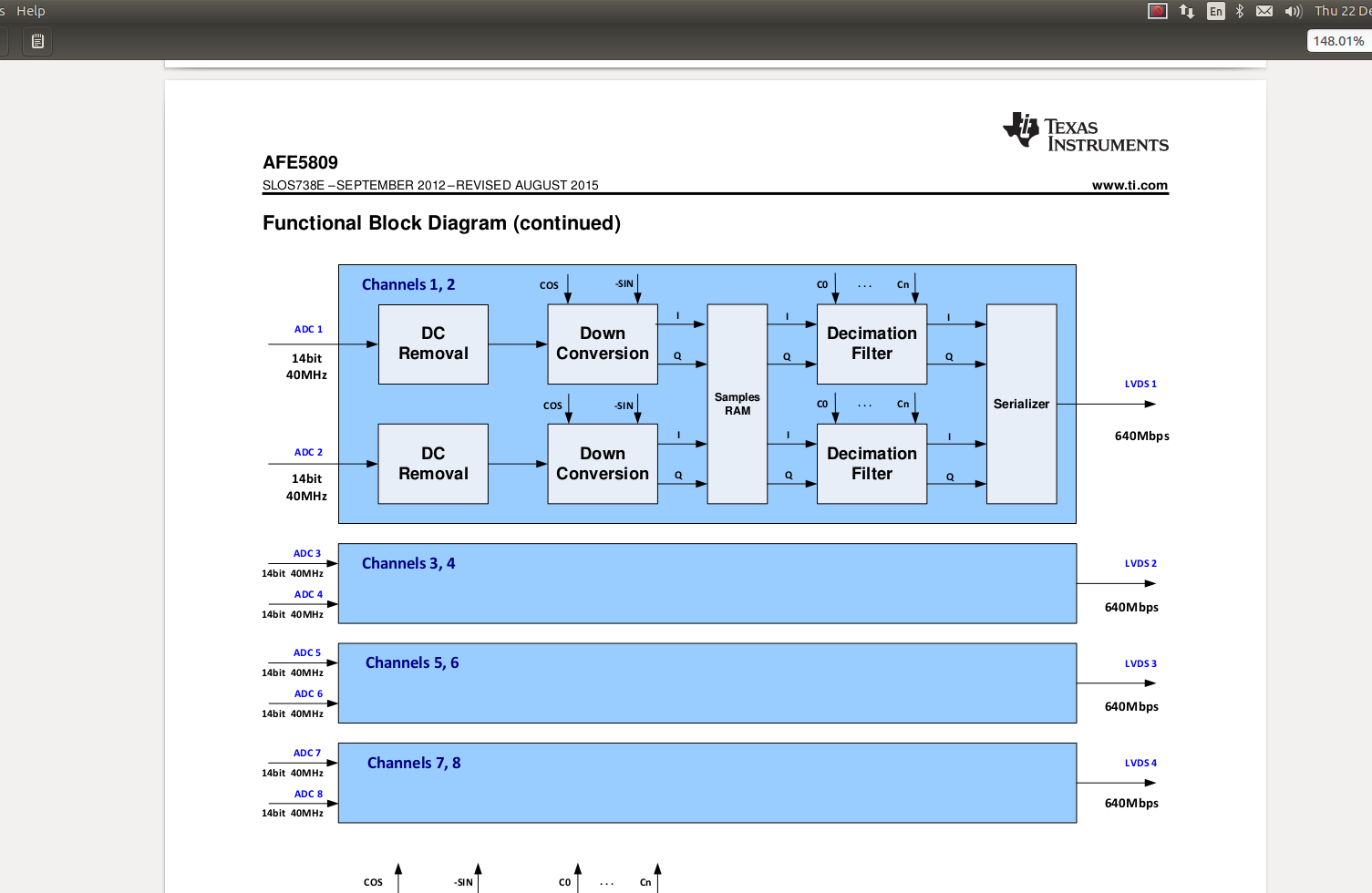
As shown in figure to configure Down Conversion block, which pin number on AFE chip should I use for cos & -sin input for Down Conversion block?  and

Coefficient of Decimation filter can be assign by using a software right?
  • Hello Vatsal,

    The input to the down converter block will be the down conversion frequency which can be programmed through the down conversion frequency (f) parameter of the profile vector or through the manual register settings. The cosine and -sine table is part of the demodulator block.
    Yes the coefficient memory can be programmed through the firmware. Refer to section 8.6.2.1 in the AFE5809 datasheet for details about the profile and coefficient RAM and the programming details.
  • Hi Praveen,
    Thanks for the info. So Do I have to generate cosine and -sine externally and give as an input to AFE? If is it the case which pin is it?

    or Does it generate its own frequency inside the chip with ADC clock?
  • Vatsal,

    You will not need to generate the cos and sine externally and provide as an input to the AFE.
    As I mentioned in my earlier post, for the down conversion block, the frequency input (ƒ) can be programmed through registers or through the profile vector. ƒ can be set with resolution Fs / 2^16, where Fs is the ADC sampling frequency.
  • Hi Praveen,
    Thank you. Now I got it. About the coefficient of the decimation filter I can access it by using software. Is there a way that I can control it by using linux?