This thread has been locked.

If you have a related question, please click the "Ask a related question" button in the top right corner. The newly created question will be automatically linked to this question.

ADS1248: NTC resistor detection solution

Part Number: ADS1248
Other Parts Discussed in Thread: ADS1247, TS3A5017, ADS124S08

Hello team,

My customer want to find a solution to detect the NTC resistor, which is similar with our ADS1248, Do you have any suggestion about the solution? Below is the datasheet of the NTC resistor, thanks

TGM-104 RT.pdf

Regards,

Nanfang

  • Nanfang,

    Measurement of an NTC thermistor is similar to measurement of a 2-wire RTD, except that the NTC thermistor may be less accurate and the temperature/resistance is not linear.

    I would start by reviewing an example measurement case using the ADS1247/8 in an application note. I have attached a link to this below. The measurement for the NTC thermistor will be similar to the Two-Wire RTD Application shown in Figure 1 on page 2.

    Looking at the application, there are several important things to note. First, if there are no leakages for the IDAC current path through the thermistor and RBIAS, the measurement is ratiometric. That means the output code will be proportional to the RTD value divided by the RBIAS value used for the reference. This way you don't have to calculate the exact voltage value. Also note that the measurement will be as accurate as the RBIAS. If RBIAS has an error, it is seen as a gain error in the measurement. Finally note that the RTD measurement has an error because of the lead resistances. For a two-wire RTD (as is the case of a thermistor), the lead resistance may not be removed. In 3-wire and 4-wire measurements, you may be able to remove some of this error, but in a two-wire measurement, it is part of the measurement.

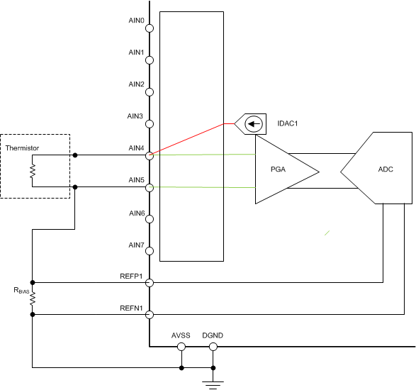
    I've drawn a diagram that shows the setup. There is a single IDAC current that goes to the input pin used for the measurement. In this diagram it is AIN4. The current flows from the thermistor to RBIAS to ground. This ADC measurement will be proportional to RNTC/RBIAS. You can use the PGA gain, which changes the proportion.

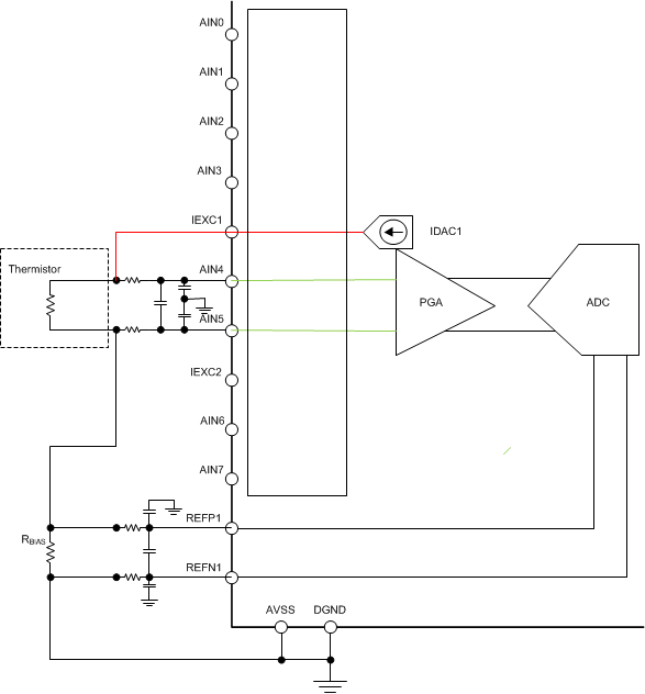
    In a second diagram, I've shown how this setup might change if you need some input filtering. Here you need an extra pin for the IDAC excitation. If you had used the original AIN4 for the IDAC, the IDAC current times the filter resistance becomes a large added error for the measurement. By having a separate output for the IDAC, we bypass the IDAC current reacting with the filter resistance.

    There are variations to this measurement. Sometimes customers use a voltage instead of a current as the excitation for the resistors. The setup may require a different topology and may need a more accurate voltage measurement.

    Often, there is an optional resistance placed in parallel with the thermistor to linearize the measurement. Your customer may or may not choose to use this linearization. It does change the equivalent resistance and there an extra calculation to get the value of the resistance of the thermistor once the ADC value is found.

    Regardless, there are several ways to make this measurement. If you have more details from the customer, we may have more input about the system.

    Joseph Wu

  • Hello Joseph,

    Thanks, The detection temperature range is from 25C to 90C, and the accuracy requirement is 2C. The NTC resistor datasheet i have shared above.

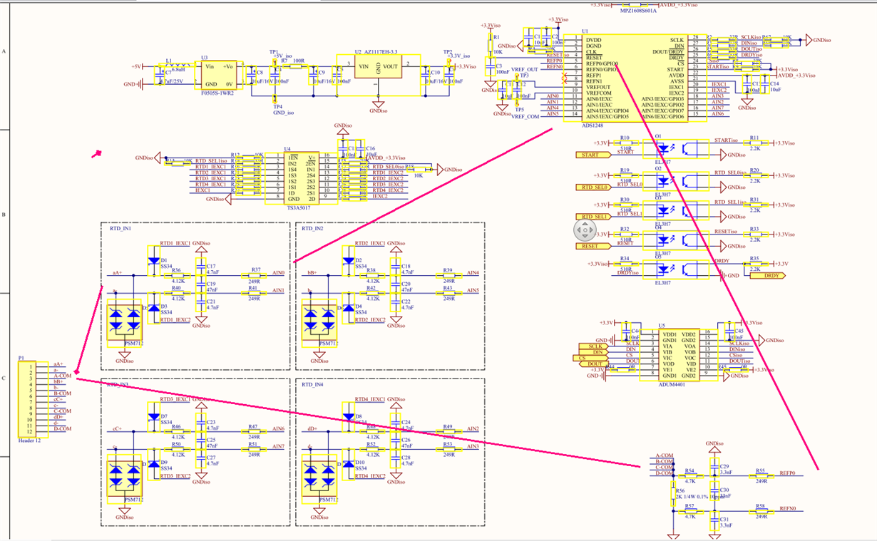
    They have designed a circuit below to detect PT100 resistor, and they use ADS1248, now they hope to modify some parts of the circuit, and make sure the circuit can detect both PT100 resistor and NTC resistor. Do you have any comments about the circuit below?

  • Nanfang,


    In general, detecting a two-wire RTD and a NTC thermistor will be the similar. It mostly depends on the range of operation and the values that you have to measure.

    At 90C, this thermistor will be about 8kΩ. At 25C it will be at 100kΩ. Note that the schematic only has a 2kΩ reference resistor. At this point the thermistor is too large of a resistance to measure. Are they planning any other changes to this measurement? If they have some sort of linearization resistor, it might lower the resistive measurement. However, I'm not sure how they plan on using such a low reference resistor.

    In addition to that, I do have some comments for the rest of the schematic.

    1. In general, I don't like to use such large bypass caps. This schematic shows 10uF for bulk capacitance. Normally, I'd use 1uF. When the power is removed, I'd prefer the device to quickly drain the charge away.

    2. I can't read the series resistance value for the excitation currents coming out of the TS3A5017. Note that it shouldn't be too large. You don't want the IDAC current source's output voltage to be to close to the positive rail. Out of curiosity, what current are they using for excitation?

    3. There is some leakage for the channels of the TS3A5017. This might make a difference in the measurement because the excitation current might go through and unused RTD or thermistor and then into the reference resistor, bypassing the RTD or thermistor that you are measuring. This will look like a gain error.

    For the TS3A5017, this current is typically 50nA which might be acceptable for the accuracy that they want. They should consider this error and calculate if this is small enough for what they want.

    4. There is also a leakage term from the PSM712. If they are using the 7V device this leakage is a maximum 20uA. That could also be a problem. In general, if the leakage on AINP and AINN are exactly the same, then this shouldn't be an issue because the error balances out. However, if they don't match, this is also an error they they need to consider.

    Note that leakages are temperature dependent. If the circuit works at room temperature, it still may have problems at higher temperatures.


    Joseph Wu
  • Hello Joseph,

    Thanks for your great support, there are some feedback about your questions below, please also give your comments.

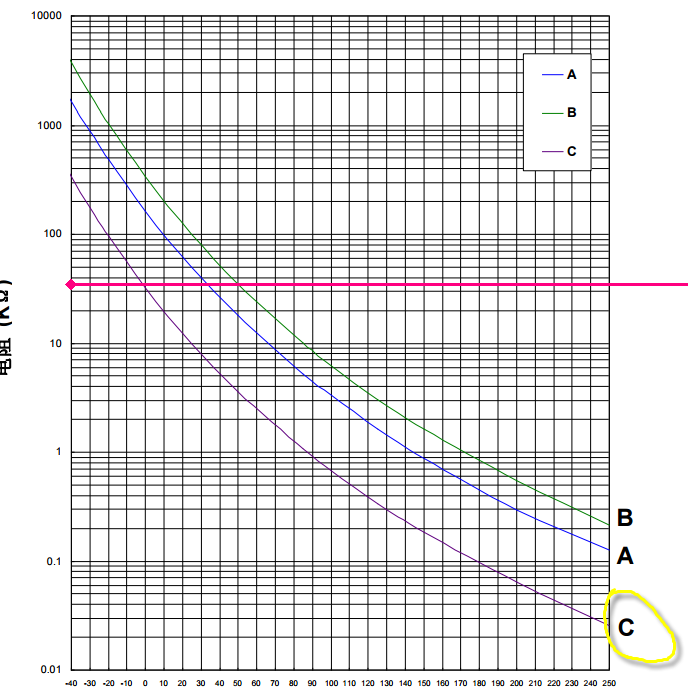
    Now they want to use TGMAA103G39HAD(purple curve), the resistor range is about from 20K to 500 ohm, what's the reference resistor they need to choose?

    2. For the series resistance coming out of the TS3A5017, now they use 0 ohm resistor, it can be adjusted according to the application.

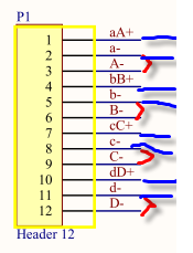
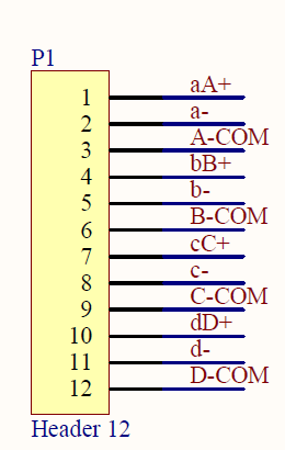
    3. Becuase this circuit is for PT100 design before, it is 3 wires, now they want to detect NTC which is 2 wires, so they need to change 3 wires to 2 wires, you can check the picture below, they short a- and A- pins, so aA+ and a- pins are 2 wires and connect to NTC.

    4. According to NTC spec, do you have any suggest solution?, i think our ADS1248 is not a good choice to detect NTC.

    5. For TS3A5017, they use it to switch 4 channles RTD, do you have reference circuit of our ADS1248 to detect 4 channels PT100? and for PSM712, do we have new solution to replace it?

    6. Can you also share the power noise spec of our ADS1248? thanks

    Regards,

    Nanfang

  • Nanfang,


    1. When you are measuring a thermistor, you compare it to the reference with a ratiometric measurement. Without any gain, the measurement becomes:

    ADC output code = 2^23 * (RRTD/RREF)

    Note that 2^23 is the maximum ADC output value. Therefore, RRTD must be smaller than or equal to RRTD. So if the RREF is 20kΩ then you would be able to measure as large as a 20kΩ RTD.

    Note that 20kΩ is a high value to be using for measuring a PT100. For the ADS1248, there are two different reference inputs that are available. REF0 and REF1. You could use two different references for the thermistor and RTD.

    2. In the last post, I noted that the leakage current for the TS3A5017 might be an issue because the typical leakage is 50nA, with a max of 1uA. Did they remove this device because of this leakage? If so, there may be other analog switches that may be available. In some of our test systems, we use low leakage optical switches for this purpose. However, I would note that these switches use several mA of current.

    There may be other solid-state switch or multiplexer options, but I don't know those products very well.

    3. That is correct. You would just be bypassing the third RTD input and the IDAC currents would then be shunted to RREF.

    4. Why do you say that the ADS1248 is not a good solution for the thermistor? The difference in magnitude between the thermistor and the RTD would be the same problem for any ADC.

    5. We don't have a reference circuit for measuring 4 three-wire RTDs. As I mentioned earlier, I don't have a good recommendation for a multiplexer or analog switch for this purpose. Note that we do have the ADS124S08, which does have extra inputs. However because it uses analog input pins for IDAC routing, it will also only handle 3 three-wire RTDs.

    As for the PSM712, I don't think there is a low leakage replacement. Most TVS devices will have a large leakage because of the size. Additionally the leakage will be larger for lower voltage devices. Most protection that I've seen involve higher series resistances and fast Schottkty diodes used to shunt extra current. I've seen the BAV99 used for this purpose, but the customer will need to review this device if they want to use it.

    6. I don't know what the power noise spec is. Are you asking about the noise that you would get if you were making measurements? I would refer to Tables 1-6 in the ADS1248 datasheet. This shows the measurement noise for different data rates and gains. The tables show the noise when the input is 0V. When measuring an input signal, note that the reference will contribute noise as well. For precision ADCs, you need to have a low noise reference.


    Joseph Wu
  • Hello Joseph,

    Thanks, i am not familiar with this part, you can find the schematic above when they use this part to detect PT100 resistor, they find the test result has big deviation, some boards the detect accuracy are OK, but some boards have big deviation.
    1. Can you help to check the schematic for PT100 application and give me some guide how to debug this problem?
    2. What is the function of Rref?
    3. When our part to detect VIN, how to calcuate Vref?

    Regards,
    Nanfang
  • Nanfang,

    First, I need more information about the deviation that they are seeing. Is this deviation they describe a large error (like they have a gain error)? or is this deviation a large amount of noise. Can you provide their data (the output data from the ADC in codes (not voltages), with the RTD resistance and reference resistance. I would also like all of their setup information, what input pins they are using, which reference input, IDAC current locations and magnitude, and data rate.

    1. I'll look over their schematic again, but I've reported most of what I've seen. To help debug this, I'll need the information I asked about in the above paragraph.

    2 and 3. The RREF is the reference of the measurement. This must be a precision resistor. In any ADC you compare the input voltage to a reference voltage and you get an output code. For a 24-bit converter,

    ADC output code = (VIN/VREF)*(2^23)

    Here I use 23 bits for positive numbers, the rest are two's complement negative numbers.

    Most RTD measurements are done with a ratiometric measurement. RREF is used for this measurement. A ratiometic measurement is shown on page 77 of the ADS1248 datasheet. It is set up like this:

    Since the same current goes through RRTD and RREF, you get this equation.

    ADC output code = (RRTD/RREF)*(2^23)

    therefore:

    RRTD = RREF*((ADC output code)/(2^23))

    This is ratiometric because you don't need to calculate the voltage of either the reference or the RTD. You only need to work with the resistances. It is very important that your RREF should be very precise. Any error in RREF is seen as a gain error. If your RREF is 1% then you already start with 1% of gain error

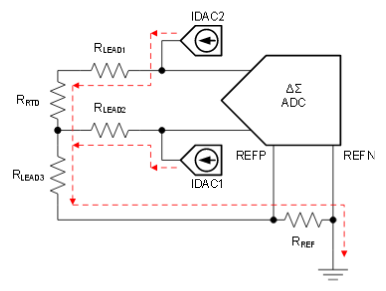
    Read through page 77 and 78 of the datasheet. I think that your customer is really using the setup from Figure 116, where the code equation is a little different because there are two IDAC currents. There may also be a little error from the mismatch of the IDAC current sources, but it does reduce the RTD lead wire resistance error.

    Note that RREF also sets the common-mode of the RTD measurement. Read through the design section of the ADS1248 datasheet starting on page 76 to get a clear picture of what your customer's design.

    Joseph Wu

  • Joseph,

    Thanks, there are some customer's applications below, please help to give your comments.

    IDAC setting: 500uA
    Ref resistor: 2k ohm
    PGA: 16

    Their test results are as below:
    1. Use resistor to simulate PT100
    2. The resistor is 100ohm(use multimeter to test it), our part AD1248 read the resistor is 100.022911 ohm
    3. Ref resistor test value is 1996.6 ohm
    4. ADC output: dac data:0x33 36 34
    5. Data rate: 20SPS

    Regards,
    Nanfang
  • Nanfang,


    These results seem reasonable. Assuming that they have settings that are used for a 3-wire RTD measurement, and they are using two IDAC currents to cancel the lead resistance error.

    With the given test setup, the result they should have is:

    Ideal Output = (100.0229 * 16)*(2^23)/(2*1996.6) = 3361927d = 334C87h

    The output that they get is 333634h or 3356212d. By dividing one from the other, you can see that there is a gain error of about 0.17%. This could be gain error from the ADC, mismatch in the IDAC currents, noise in the measurement, or even error in the resistance measurements.

    Note that they have given just one data point. If you look in the ADS1248 datasheet, the application example shows inputs for 20 different resistor values from 20Ω to 400Ω

    I've done similar tests and I always use precision resistors for both the input and the reference. Drift error from the resistors is a big problem in this measurements, and typically, the precision resistors I use have a drift of less than 5ppm/C.


    Joseph Wu

  • Hello Joseph,

    Thanks, These results that i shared with you last time seem reasonable. But for another board, the design is the same, and the settings are also same, but gain error is much higher, so Huawei ask what's the reason, do you hava any suggestion?

    Their test results are as below:

    1. The resistor is 100.01ohm(use multimeter to test it), our part AD1248 read the resistor is 100.251106 ohm
    2. ADC output: dac data:0x33541d


    Regards,
    Nanfang
  • Hello Joseph,

    Do you have any comments about these data? thanks

    Regards,
    Nanfang
  • Hello Joseph,

    Thanks, These results that i shared with you last time seem reasonable. But for another board, the design is the same, and the settings are also same, but gain error is much higher, so Huawei ask what's the reason, do you hava any suggestion?

    Their test results are as below:

    1. The resistor is 100.01ohm(use multimeter to test it), our part AD1248 read the resistor is 100.251106 ohm
    2. ADC output: dac data:0x33541d


    Regards,
    Nanfang
  • Nanfang,


    Sorry, I was out of the office for the last half of last week.

    First, I would check the result with a several resistors. Getting results from different points will determine if the error is a gain error or an offset. If the error is an offset, then an offset calibration may help.

    If the error is gain error a gain calibration might help. However, with the ADS1248, the gain is trimmed at the factory for each PGA gain and the default gain setting is very good.

    There are two things to check if there is a significant gain error. First, make sure that the reference resistor is absolutely correct. If the resistor is 100.01Ω, and the ADS1248 reads 100.25Ω, then it is possible that the reference resistor is smaller than expected by about 0.24%. I would note that in the schematic, the reference resistor is 0.1%, and this is a large part of the error budget. To be sure, I would have them measure the reference resistor to know what contribution the reference has to this error.

    The second thing that may cause this gain error is a mismatch between the IDAC currents. Note that only one of the IDAC currents goes to the RTD and the other IDAC current is only used to cancel the resistance. However, both currents go to the reference resistor. If the IDAC currents are mismatched by 0.5%, then you may see 0.25% error in the RTD measurement.

    To verify this error, first set the output for IDAC1 and IDAC2, and make the first measurement. Then swap the IDAC current outputs so that the IDAC2 replaces IDAC1 and IDAC1 replaces IDAC2 and take the measurement again. Once you make the two measurements, take the average. This should remove the IDAC mismatch error.


    Joseph Wu
  • Hello Joseph,

    I get some feedback from customer below, please help to give your comments, thanks

    PT100 resistor ADS1248 value dac data REF resistor
    170.02 170.475662 0x574896 1996.6
    160.01 160.320343 0x521582 1996.6
    150.02 150.2724 0x4cf081 1996.6
    140.02 140.443771 0x47e83f 1996.6
    120.03 120.368866 0x3da0fd 1996.6
    110.02 110.327095 0x387ccb 1996.6
    99.999 100.276772 0x33577a 1996.6
    80.042 80.201324 0x291026 1996.6
    70.041 70.16951 0x23ed42 1996.6

    Regards,
    Nanfang
  • Nanfang,


    Have they tried swapping the IDAC current sources and averaging the result? This was one of my suggestions from the last post.

    Since an IDAC mismatch may look like a gain error, and their result looks like a small gain error, they should try this to see if the error is significantly reduced.


    Joseph Wu
  • Hello Joseph,

    Thanks, can you tell me how to swap the IDAC current sources and averaging the result?

    Regards,
    Nanfang
  • Nanfang,

    I didn't have a chance to clearly look at the data last night, and now that I've entered the data into a spreadsheet, the error is more random than a gain error. I took the data that you last posted and made some calculations. You can see the result in the table below.

    RTD value (Ω)

    ADC code (hex) ADC code (decimal) ADC meas (Ω) ADC error (Ω)
    170.02 574896 5720214 170.1859 -0.16585
    160.01 521582 5379458 160.0478 -0.0378
    150.02 4CF081 5042305 150.0169 0.003064
    140.02 47E83F 4712511 140.205 -0.18502
    120.03 3DA0FD 4038909 120.1642 -0.13424
    110.02 387CCB 3701963 110.1395 -0.11954
    99.999 33577A 3364730 100.1063 -0.1073
    80.042 291026 2691110 80.06499 -0.02299
    70.041 23ED42 2354498 70.05022 -0.00922

    In the first column is the resistor measurement from the multimeter. What multimeter is used to make this measurement? Is this from a four-wire measurement? It is important that this measurement is accurate, since we are comparing the ADC result to this value.

    In the second column, is the ADC output code in hex from your last post. In the third column is that data converted to decimal. Using the ADC data, I convert this to the ADC measured resistance. You take the number from the third column, divide by the 2^23, and the PGA of 8, then multiply by the reference resistance (1996.6). This calculated resistance is in the fourth column. Note that it is different than the values that you gave in your data your previous post. If they have a different method of calculating the resistance, I would like to know how they got their values. Note that the values in your post show a small gain error (the error between ADC measurement and resistor value measurement gets larger as the resistance values get larger).

    In the fifth column, I calculate the error in the measurement in ohms. In this case, the error seems more random.  If you plot these values, the error doesn't necessarily get larger with the resistance. I've plotted this error in the graph below.

    Out of curiosity, what type of resistors are these? Are they different types of resistors? Is there possibly a difference in self-heating? Depending on the temperature drift of the resistors, this might be a factor. If the 150Ω and 160Ω resistances are different, then this might be what the graph shows.

    Going back to your question about swapping the IDAC current sources, I mentioned this in one of my previous posts. You basically swap the IDAC current sources. First set the output for IDAC1 and IDAC2, and make the first measurement. Then swap the IDAC current outputs so that the IDAC2 replaces IDAC1 and IDAC1 replaces IDAC2 and take the measurement again. Once you make the two measurements, take the average. This should remove the IDAC mismatch error.

    Using the schematic you provided in one of the first posts, let's say that you use the AIN0 and AIN1 measurement.

    Then let's say that IDAC1 goes to RTD1_IEXC1 and that IDAC2 goes to RTD1_IEXC2. Then you take the measurement. After that you would send IDAC1 to RTD1_IEXC2 and then IDAC2 to RTD1_IEXC1. This would swap the IDAC outputs. Then you take a second measurement and average that with the first measurement. If IDAC1 and IDAC2 did not match, then this would average out any gain error seen from the mismatch.

    Joseph Wu

  • Hello Joseph,

    Thanks, customer is doing the test and will give us feedback. Customer ask what's the accuracy of IDAC1 and IDAC2?

    Regards,
    Nanfang
  • Nanfang,


    There are two IDAC errors that are of concern when making measurements with the IDAC currents. Both are listed in the datasheet in the electrical characteristics table.

    First, the typical IDAC error in absolute current is only ±1%. However, in a ratiometric measurement with only one IDAC current, this error is not a factor in the measurement. If the RTD and the reference resistor have the same current, then the IDAC current error cancels. The output code is a ratio of only the RTD to the reference resistor. Note that there cannot be any current leakage between the RTD and reference resistor, or the leakage becomes a gain error.

    Second, if the customer uses two IDAC currents in the RTD measurement so that the lead resistances can be cancelled in the measurement, then the IDAC current mismatch error becomes a concern. For the ADS1248, the typical IDAC mismatch error is 0.15%. This error would be seen as a gain error. As I mentioned in a previous post, this error can be removed by swapping the IDAC currents and averaging the measurement result.

    I had asked this in the previous post, but what type resistors are they using to test the measurement accuracy? I'd like to know the manufacturer and series.


    Joseph Wu
  • Hello Joseph,

    Thanks, customer use resistance box to simulate RTD resistor, the accuracy of the resistance box is 1%. When they start to do the test, they use high performance multimeter "Agilent 34411A 61/2 digit multimeter" to test the resistor value of the output of resistance box.

    After changing the IDAC1 and IDAC2, the test result is as below, please help to give your comments.

    Huawei also test IDAC current, they use high performance multimeter to test the current, I1=0.49625mA, I2=0.49953mA

    Test method: I1: connect one port to A-com pin and connect another port to aA+ pin in serial

                          I2: connect one port to A-com pin and connect another port to a- pin in serial

    Regards,

    Nanfang

  • Nanfang,


    Sorry, I must have missed your last E2E post. I'll answer the questions as you numbered them in the email that you sent me.

    1. With the numbers you sent in the last email, the device is not out of specification. The error looks to be typical for the IDAC. The IDAC current accuracy is 1% typical, and 6% maximum. In the case you mention, the IDAC current is set to 500uA, and you get 495.52uA, which is about 1% error. This should be an expected value. Did you write the correct current value in the last email?

    2. a. They shouldn't have to change their hardware to swap IDAC1 and IDAC2 outputs. It can be done with just the registers and are independently set. If you go to the datasheet on page 63, IDAC Control Register 1 sets where each IDAC goes. I1DIR[3:0] sets IDAC1, and I2DIR[3:0] sets IDAC2.

    As an example, if you set IDAC1 to the IEXC1 pin and IDAC2 to the IEXC2 pin. Then you would write 10001001b to IDAC Control Register 1. Then if you want to swap the IDAC outputs, you would set IDAC1 to the IEXC2 pin and IDAC2 to the IEXC1 pin. To change this you would write 10011000b to the IDAC Control Register. This would be a simple register write and there is no need to change hardware settings.

    2. b. If they want to get the best possible accuracy from the measurement, they will need to swap the IDAC currents to get rid of the IDAC mismatch error. From the measurements that you give in the excel screen shot, I have my own excel calculation:

    IDAC setting 1 IDAC setting 2 (swapped)
    PT100 ADC read ADC read REF ADC (*) PT100 ADC read ADC read REF ADC (*) Averaged
    99.852 32FE2A 3341866 1995.3 99.36131879 99.852 335BFB 3365883 1995.3 100.0753991 99.71835896
    99.852 32EE96 3337878 1998 99.37703973 99.852 33490F 3361039 1998 100.0666011 99.7218204
    99.852 32DB91 3333009 2001.3 99.39597415 99.852 3336FB 3356411 2001.3 100.0938614 99.7449178
    *Using REF value (not 2000 Ω)

    It looks as if they have some small residual error of about .01 Ω to .03 Ω. This could be an offset, or it could be a gain error. This value is a bit large for a gain error, but it is possible. It could also be a small error in the REF input measurement. There is also the possibility of some mismatch leakage from the way the IDAC currents are multiplexed.


    Joseph Wu
  • Nanfang,

    The excel table didn't format the way I thought it would. I'll copy the file into this post. You can see how the calculations are made from the individual cells in the spreadsheet.

    Joseph Wu

    IDAC swap.xlsx

  • Hello Joseph,

    Got it, it is very clear, it seems that our customer all test results are reasonable, thanks for your great support.

    Regards,
    Nanfang
  • Hello Josehp,

    Yes, I find the IDAC current accuracy is 6% maximum in latest datasheet.
    The absolute mismatch between IDACs is 0.15%(typ), what's the max value?
    You suggest customer to sweep IDAC1 and IDAC2, then average the test result, so customer needs to do two test, you know there should be some time between the two tests, dose the time impact the detect accuracy? how long time do you suggest about the two test? thanks

    Regards,
    Nanfang
  • Nanfang,


    We do not list a maximum value. However I would guess that since the 0.15% mismatch is a typical value, it would be roughly a single standard deviation.

    When the IDAC1 and IDAC2 are enabled (or if they are swapped), the current from the IDAC should be turned on immediately. However, there may be some settling time required because of any capacitance seen by the RTD or reference resistors. For example there is some capacitance associated with the filters. The AIN0 to AIN1 input will have an RC settling time coming from C19 (and any capacitance coming from the TVS diodes) reacting with R36, R40, and the RTD resistance. The REF0 inputs will have an RC settling from C30 combined with R54, R57, and the reference resistor R56.


    Joseph Wu
  • Nanfang,

    I'm answering your email about IDAC current swapping here:

    By swapping the IDAC currents, the measurement should have no error from IDAC current values, even if both IDAC currents are well below the expected current. The IDAC mismatch errors cancel and primary error in the measurement is in the reference resistor value. As a ratiometric measurement, the measurement never relies on the exact voltage from the measurement, but is shown as a ratio between the resistance of the RTD and the reference resistor.

    Here is an example of the measurement. I'll use Figure 116 in the ADS1248 datasheet to show how the measurement works.

    Using this figure, the ADC will read a voltage based on the currents from IDAC1 and IDAC2. Here, I will ignore the PGA gain. The ADC will read:

    ADC output = [IDAC1*(RLEAD1+RRTD)-(IDAC2*RLEAD2)]*(2^23)/[(IDAC1+IDAC2)*RREF]     (1)

    If IDAC1=IDAC2 and RLEAD1=RLEAD2, then the ADC output = RRTD*2^23/(2*RREF) which becomes very simple to determine the RTD value. However, if IDAC1≠IDAC2, you can use swapping to remove the mismatch error.

    With equation (1), we have the first measurement. Now we swap IDAC1 and IDAC2 as shown in the figure below, which gives a slightly different output.

    ADC output = [IDAC2*(RLEAD1+RRTD)-(IDAC1*RLEAD2)]*(2^23)/[(IDAC1+IDAC2)*RREF]     (2)

    To swap and average we take equation (1), add this to equation (2) and then divide by 2 to average the result. This is shown below.

    Averaged ADC output = [[IDAC1*(RLEAD1+RRTD)-(IDAC2*RLEAD2)]+[IDAC2*(RLEAD1+RRTD)-(IDAC1*RLEAD2)]]*(2^23)/[2*[(IDAC1+IDAC2)*RREF]]     (3)

    Then combine IDAC1+IDAC2 terms:

    Averaged ADC output = [(IDAC1+IDAC2)*(RLEAD1+RRTD)-(IDAC1+IDAC2)*RLEAD2)]]*(2^23)/[2*(IDAC1+IDAC2)*RREF]     (4)

    Then you cancel the IDAC1+IDAC2 terms and then set RLEAD1=RLEAD2=RLEAD to get the equations below.

    Averaged ADC output = [(RLEAD+RRTD)-RLEAD)]]*(2^23)/(2*RREF)]     (5)

    After this the RLEAD terms are cancelled as well.

    Averaged ADC output = RRTD*(2^23)/(2*RREF)     (6)

    Going through the results to equation (6), you can see that it doesn't matter that IDAC1 and IDAC2 are not equal, it just matters that IDAC1 and IDAC2 are the same values after they are swapped. If they are the same then (IDAC1+IDAC2) terms cancel out.

    There may still be errors in the system. Here we've assumed that RLEAD1 and RLEAD2 are the same. If they are different, this becomes an error. Also, if there are any leakage currents in the measurement (like TVS diodes for example), then this becomes an error term. However, going back to (6), the biggest error comes from the error in RREF. That is why RREF must be a precision resistor.

    Joseph Wu