This thread has been locked.

If you have a related question, please click the "Ask a related question" button in the top right corner. The newly created question will be automatically linked to this question.

ADS1120: Minimum time ADS1120 could work

Guru 16770 points
Part Number: ADS1120
Other Parts Discussed in Thread: ADS1220

Hi

We want to know the minimum time that ADS1120 could work for the following as far as possible.

1. Powered up
2. Reading data
3. Powered down

We want to complete the upper sequence as quickly as possible since we intend to use this device with energy harvesting.

It is OK the data we need is a brief moment data.

How can we estimate minimum time for 1 - 2 - 3 ?
What kind of delay should we consider?

BestRegards

  • Hi na na 78,

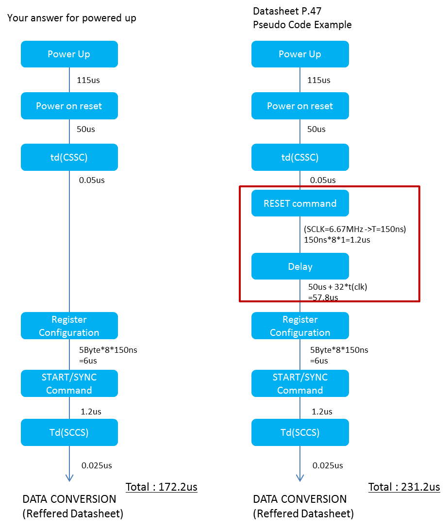
    I will assume that you are talking about complete power supply power up and power down to the ADS1120.  To ensure proper power up, the supply ramp must be no faster than 1V/50us.  For minimum power supply voltage of 2.3V (lowest voltage the ADS1120 will operate) you would require a minimum ramp time of 115us (2.3*50us).  Once the device is at nominal operating voltage, you must wait an additional 50us for internal circuitry to complete the power on reset before communicating to the device.

    The ADS1120 device register configuration will take time and the length of time will depend on the SCLK frequency used and the number of registers written. The maximum frequency for SCLK is 6.67MHz resulting in a minimum SCLK period of 150ns. The WREG (write register) command is 1 byte, and there are 4 registers with each register 1 byte in length.  5 bytes times 8 SCLKs per byte result in 6us (5x8x150ns) as a very minimum using continuous clocking.  If toggling CS (and CS is not connected to GND), then you must wait an additional 50ns from the falling edge of CS to the first rising edge of SCLK.  A hold time is also required at 25ns after the last falling edge of SCLK to the rising edge of CS.  After configuration is complete, the START/SYNC command should be sent.  This is a one byte command (1x8x150ns) taking about 1.2us to complete. 

    So for 1, the time is 115us +50us + 7.2us, or 172.2us from initial power on to start of conversion using the new register settings. 

    The length of time for conversion will depend on the data rate chosen and whether normal mode or turbo mode is selected.  The length of conversion times are listed in Table 11 on page 27 of the ADS1120 datasheet.  The times are given in tclk cycles, so keep in mind that when using the internal oscillator the period can vary by +/- 2% of the nominal.

    When the conversion period is complete, DRDY will transition low.  At that time the data can be read from the ADS1120 by sending 16 SCLKs. The length of time to read out the data will be the time it takes for the processor to recognize DRDY has transitioned and the data read. Read time is 2.4us (16x150ns) minimum. A read data command does not need to be issued.

    For 2, the time will be 2.4us and the length of time it takes the processor to recognize DRDY has fallen.

    As soon as the result is read, then the device can be powered down. So for 3, the time is just the rate of supply decay.

    Now this timing is making a huge assumption, and that assumption is what ever is being measured is ready to be measured.  If there is a powered sensor, or some external reference involved or any analog input filtering, then before sending the START/SYNC command the analog signals need to be settled.  You will need to consider this additional time for your total on time.

    As far as power is concerned, the normal operation is for the ADS1120 to start, take one conversion and then go to a low power state.  The default is 20sps at power up, so the device will start converting immediately and if the registers are not reconfigured right away, the conversion will end in about 50ms with DRDY transitioning from high to low.

    Best regards,

    Bob B

  • Hi Bob

    Thank you for your detail explanation.

    >The supply ramp must be no faster than 1V/50us

    Is it a specific characteristics of ADS1120? Or is it common to all products?

    And, according to your answer, I made the following flow charts.

    I made the right figure which would show the pseudo code example.

    The red square is the differences between pseudo code example and your answer.

    Is it no problem not to consider sending RESET command and the delay after RESET?

    BestRegards

  • Hi na na 78,

    The supply ramp rate is required for the ADS1120 and ADS1220 devices only to ensure proper startup over the full temperature range of these devices.

    The RESET command is optional.  If you follow the ramp rate recommendation, then you should have no need to add an additional RESET command as the power on reset (POR) accomplishes the same reset action as the command.  This decision is entirely up to you.  It does not hurt you to give the RESET command other than additional power that is consumed by adding the RESET command and the time to accomplish the reset.

    Best regards,

    Bob B