


Hello, I currently have an MSP430 blue-wired to the AFE4404EVM shown through the block diagram below.

At the moment, I have been trying to use I2C communications with the AFE4404, but I am not getting a response at all. After the blue-wiring, the AFE4404EVM is not recognized by a computer and the external sensor does not light up when it is plugged in.
The steps that I have taken to debug this issue are:
Plugged the AFE4404 into the computer – It was not recognized at all; It did not show up in the device manager, and LED1 is the only one that lights up. The external sensor does not light up at all. This has been tested on multiple computers.
My teammate Victoria probed the AFE4404 board for shorts that may have occurred because of soldering and desoldering, but she didn’t find any.
I have made sure that the AFE_RESETZ is always set to high.
I have checked for the ADC_RDY pin to go high, but it does not go high at all.
For I2C:
During my tests, I have been able to obtain these waveforms of I2C coming from the MSPEXP430G2553LP:
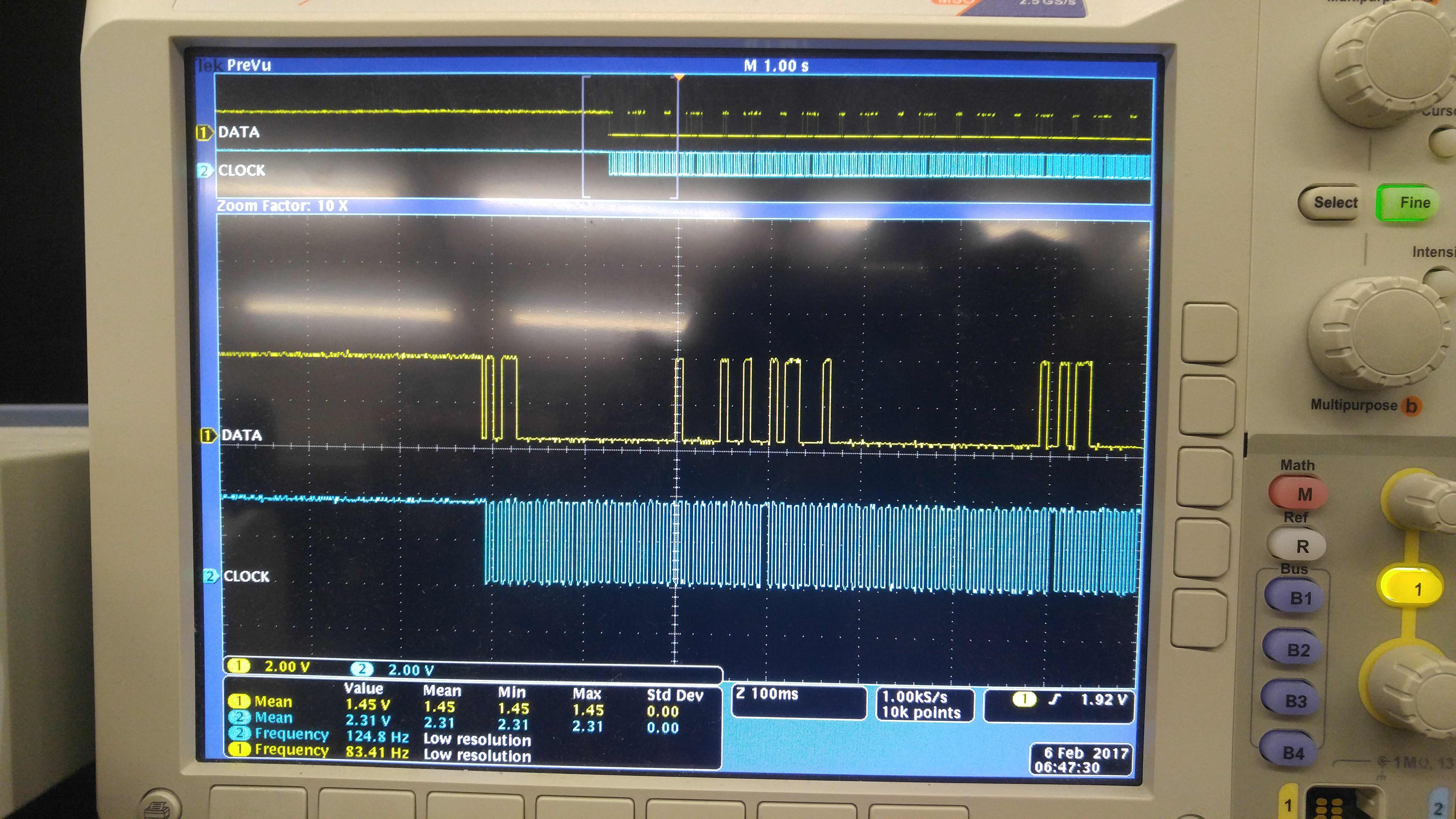
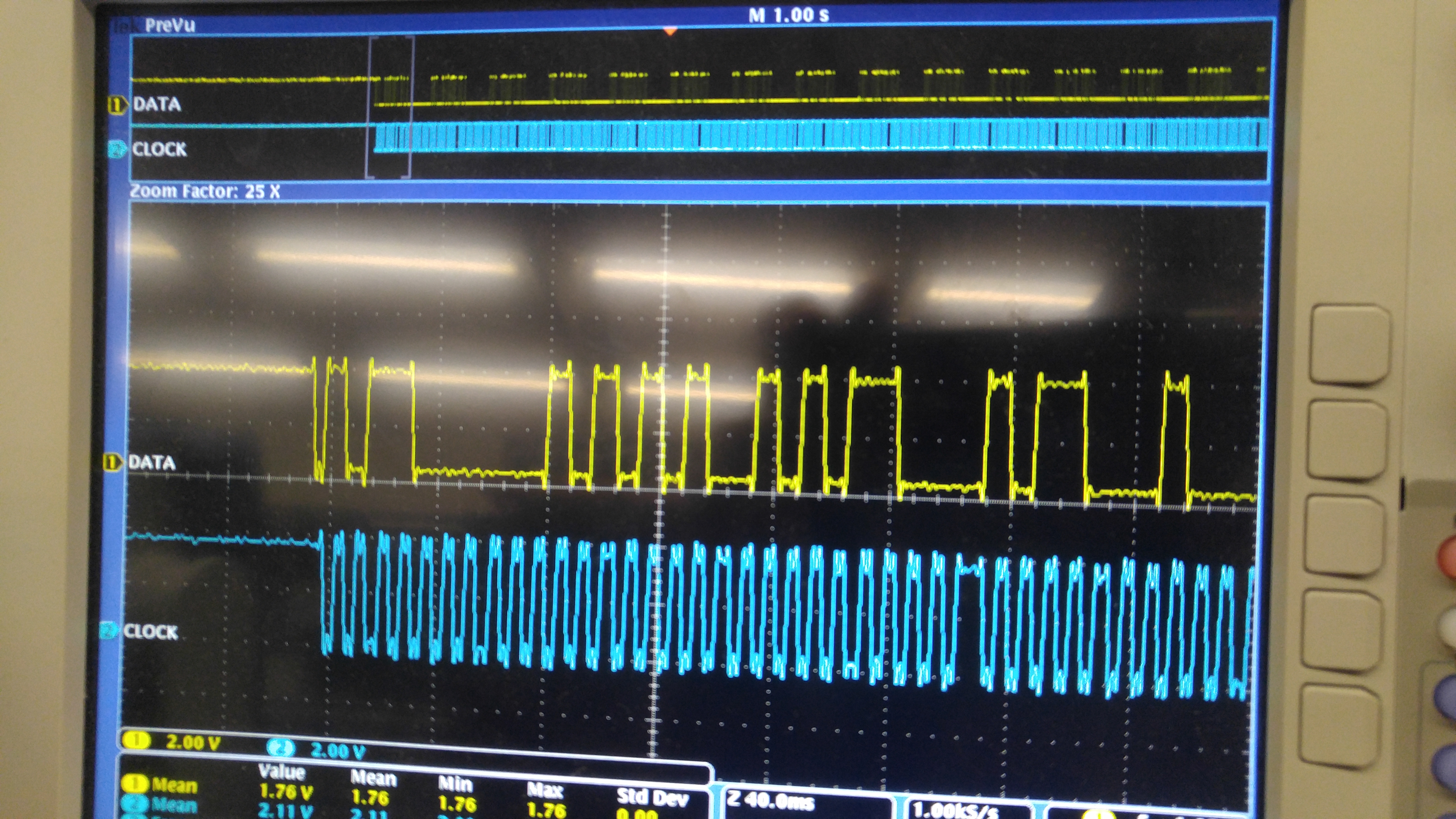
I have seen that the start and stop conditions are met for the I2C protocol.
The code that I am using is a modified version of one of the examples for I2C between MSP430 MCUs. It demonstrates transferring and receiving bits through I2C. When I stepped through the modified code, it was able to transfer the bits that I wanted it to send, but it does not receive any bits back from the AFE. I have altered the code to write to the ninth and tenth registers to try and turn on LED2, but nothing happened. I am not sure if I have approached it right or not, and I have attached the current version of the code that I was using. Another thing is that the GND that we are using is not the same ground that was in the MCU blue-wire document, and that the resistors are 11k because there weren't any 10k resistors available during testing. I have also attached a zip of the current version of the code that I was using for testing.
Below, I have attached a copy of the example that I have modified to get the first waveform that I have shown above. Have I gone about the right way to try and get data from the specific registers on the AFE4404EVM? I have checked the datasheet and found the timing registers, but I am not sure what I need to write to turn on the LEDs for example or read information from specific registers.
/* --COPYRIGHT--,BSD_EX
 * Copyright (c) 2012, Texas Instruments Incorporated
 * All rights reserved.
 *
 * Redistribution and use in source and binary forms, with or without
 * modification, are permitted provided that the following conditions
 * are met:
 *
 * *  Redistributions of source code must retain the above copyright
 *    notice, this list of conditions and the following disclaimer.
 *
 * *  Redistributions in binary form must reproduce the above copyright
 *    notice, this list of conditions and the following disclaimer in the
 *    documentation and/or other materials provided with the distribution.
 *
 * *  Neither the name of Texas Instruments Incorporated nor the names of
 *    its contributors may be used to endorse or promote products derived
 *    from this software without specific prior written permission.
 *
 * THIS SOFTWARE IS PROVIDED BY THE COPYRIGHT HOLDERS AND CONTRIBUTORS "AS IS"
 * AND ANY EXPRESS OR IMPLIED WARRANTIES, INCLUDING, BUT NOT LIMITED TO,
 * THE IMPLIED WARRANTIES OF MERCHANTABILITY AND FITNESS FOR A PARTICULAR
 * PURPOSE ARE DISCLAIMED. IN NO EVENT SHALL THE COPYRIGHT OWNER OR
 * CONTRIBUTORS BE LIABLE FOR ANY DIRECT, INDIRECT, INCIDENTAL, SPECIAL,
 * EXEMPLARY, OR CONSEQUENTIAL DAMAGES (INCLUDING, BUT NOT LIMITED TO,
 * PROCUREMENT OF SUBSTITUTE GOODS OR SERVICES; LOSS OF USE, DATA, OR PROFITS;
 * OR BUSINESS INTERRUPTION) HOWEVER CAUSED AND ON ANY THEORY OF LIABILITY,
 * WHETHER IN CONTRACT, STRICT LIABILITY, OR TORT (INCLUDING NEGLIGENCE OR
 * OTHERWISE) ARISING IN ANY WAY OUT OF THE USE OF THIS SOFTWARE,
 * EVEN IF ADVISED OF THE POSSIBILITY OF SUCH DAMAGE.
 *
 *******************************************************************************
 *
 *                       MSP430 CODE EXAMPLE DISCLAIMER
 *
 * MSP430 code examples are self-contained low-level programs that typically
 * demonstrate a single peripheral function or device feature in a highly
 * concise manner. For this the code may rely on the device's power-on default
 * register values and settings such as the clock configuration and care must
 * be taken when combining code from several examples to avoid potential side
 * effects. Also see www.ti.com/grace for a GUI- and www.ti.com/msp430ware
 * for an API functional library-approach to peripheral configuration.
 *
 * --/COPYRIGHT--*/
//******************************************************************************
//  MSP430G2xx3 Demo - USCI_B0 I2C Master TX/RX multiple bytes from MSP430 Slave
//                     with a repeated start in between TX and RX operations.
//
//  Description: This demo connects two MSP430's via the I2C bus. The master
//  transmits to the slave, then a repeated start is generated followed by a
//  receive operation. This is the master code. This code demonstrates how to
//  implement an I2C repeated start with the USCI module using the USCI_B0 TX
//  interrupt.
//  ACLK = n/a, MCLK = SMCLK = BRCLK = default DCO = ~1.2MHz
//
//	***to be used with msp430x22x4_uscib0_i2c_13.c***
//
//                                /|\  /|\
//               MSP430F24x      10k  10k     MSP430G2xx3
//                   slave         |    |        master
//             -----------------   |    |  -----------------
//           -|XIN  P3.1/UCB0SDA|<-|---+->|P3.1/UCB0SDA  XIN|-
//            |                 |  |      |                 |
//           -|XOUT             |  |      |             XOUT|-
//            |     P3.2/UCB0SCL|<-+----->|P3.2/UCB0SCL     |
//            |                 |         |                 |
//
//  D. Dang
//  Texas Instruments Inc.
//  February 2011
//  Built with CCS Version 4.2.0 and IAR Embedded Workbench Version: 5.10
//******************************************************************************
#include <msp430.h>

#define NUM_BYTES_TX 3                         // How many bytes?
#define NUM_BYTES_RX 3

int RXByteCtr, RPT_Flag = 0;                // enables repeated start when 1
volatile unsigned char RxBuffer[128];       // Allocate 128 byte of RAM
unsigned char *PTxData;                     // Pointer to TX data
unsigned char *PRxData;                     // Pointer to RX data
unsigned char TXByteCtr, RX = 0;

const unsigned char TxData[] =              // Table of data to transmit
{
  0x00,
  0x01,
  0x09, //LED2 Start
  0x0F//, //LED2 Turn on?
  //0x0A, // LED2 End       // uncommenting this stops the communication from looping
  //0x0F // LED2 Turn off?
};

void Setup_TX(void);
void Setup_RX(void);
void Transmit(void);
void Receive(void);

int main(void)
{
  WDTCTL = WDTPW + WDTHOLD;                 // Stop WDT
  P1DIR |= BIT4;                            // P1.4 output
  P1SEL |= BIT6 + BIT7;                     // Assign I2C pins to USCI_B0
  P1SEL2|= BIT6 + BIT7;                     // Assign I2C pins to USCI_B0
  P1OUT |= 0x01;                            //P1.4 = 1 for AFE_RESETZ

  while(1){

  //Transmit process
  Setup_TX();
  RPT_Flag = 1;
  Transmit();
  while (UCB0CTL1 & UCTXSTP);             // Ensure stop condition got sent

  //Receive process
  Setup_RX();
  Receive();
  while (UCB0CTL1 & UCTXSTP);             // Ensure stop condition got sent
  }
}

//-------------------------------------------------------------------------------
// The USCI_B0 data ISR is used to move received data from the I2C slave
// to the MSP430 memory. It is structured such that it can be used to receive
// any 2+ number of bytes by pre-loading RXByteCtr with the byte count.
//-------------------------------------------------------------------------------
#if defined(__TI_COMPILER_VERSION__) || defined(__IAR_SYSTEMS_ICC__)
#pragma vector = USCIAB0TX_VECTOR
__interrupt void USCIAB0TX_ISR(void)
#elif defined(__GNUC__)
void __attribute__ ((interrupt(USCIAB0TX_VECTOR))) USCIAB0TX_ISR (void)
#else
#error Compiler not supported!
#endif
{
  if(RX == 1){                              // Master Recieve?
  RXByteCtr--;                              // Decrement RX byte counter
  if (RXByteCtr)
  {
    *PRxData++ = UCB0RXBUF;                 // Move RX data to address PRxData
  }
  else
  {
    if(RPT_Flag == 0)
        UCB0CTL1 |= UCTXSTP;                // No Repeated Start: stop condition
      if(RPT_Flag == 1){                    // if Repeated Start: do nothing
        RPT_Flag = 0;
      }
    *PRxData = UCB0RXBUF;                   // Move final RX data to PRxData
    __bic_SR_register_on_exit(CPUOFF);      // Exit LPM0
  }}

  else{                                     // Master Transmit
      if (TXByteCtr)                        // Check TX byte counter
  {
    UCB0TXBUF = *PTxData++;                 // Load TX buffer
    TXByteCtr--;                            // Decrement TX byte counter
  }
  else
  {
    if(RPT_Flag == 1){
    RPT_Flag = 0;
    PTxData = (unsigned char *)TxData;                      // TX array start address
    TXByteCtr = sizeof TxData;                 // Load TX byte counter
    __bic_SR_register_on_exit(CPUOFF);
    }
    else{
    UCB0CTL1 |= UCTXSTP;                    // I2C stop condition
    IFG2 &= ~UCB0TXIFG;                     // Clear USCI_B0 TX int flag
    __bic_SR_register_on_exit(CPUOFF);      // Exit LPM0
    }
  }
 }

}

void Setup_TX(void){
  __disable_interrupt();
  BCSCTL1 = CALBC1_8MHZ;                   // set clock speed to 8MHz
  DCOCTL = CALDCO_8MHZ;
  RX = 0;
  IE2 &= ~UCB0RXIE;
  while (UCB0CTL1 & UCTXSTP);               // Ensure stop condition got sent// Disable RX interrupt
  UCB0CTL1 |= UCSWRST;                      // Enable SW reset
  UCB0CTL0 = UCMST + UCMODE_3 + UCSYNC;     // I2C Master, synchronous mode
  UCB0CTL1 = UCSSEL_2 + UCSWRST;            // Use SMCLK, keep SW reset
  UCB0BR0 = 1;                           //set clock to 8MHz with 9800 baud
  UCB0BR1 = 0;							//set clock to 8MHz with 9800 baud
//  UCB0BR0 = 12;                             // fSCL = SMCLK/12 = ~100kHz
//  UCB0BR1 = 0;
  UCB0I2CSA = 0x58;                         // Slave Address is 058h
  UCB0CTL1 &= ~UCSWRST;                     // Clear SW reset, resume operation
  IE2 |= UCB0TXIE;                          // Enable TX interrupt
}
void Setup_RX(void){
  __disable_interrupt();
  BCSCTL1 = CALBC1_8MHZ;                   // set clock speed to 8MHz
  DCOCTL = CALDCO_8MHZ;
  RX = 1;
  IE2 &= ~UCB0TXIE;
  UCB0CTL1 |= UCSWRST;                      // Enable SW reset
  UCB0CTL0 = UCMST + UCMODE_3 + UCSYNC;     // I2C Master, synchronous mode
  UCB0CTL1 = UCSSEL_2 + UCSWRST;            // Use SMCLK, keep SW reset
  UCB0BR0 = 1;                           //set clock to 8MHz with 9800 baud
  UCB0BR1 = 0;							//set clock to 8MHz with 9800 baud
  UCB0I2CSA = 0x58;                         // Slave Address is 058h
  UCB0CTL1 &= ~UCSWRST;                     // Clear SW reset, resume operation
  IE2 |= UCB0RXIE;                          // Enable RX interrupt
}
void Transmit(void){
	PTxData = (unsigned char *)TxData;                     // TX array start address
	TXByteCtr = sizeof TxData;                  // Load TX byte counter
    while (UCB0CTL1 & UCTXSTP);             // Ensure stop condition got sent
    UCB0CTL1 |= UCTR + UCTXSTT;             // I2C TX, start condition
    __bis_SR_register(CPUOFF + GIE);        // Enter LPM0 w/ interrupts
}
void Receive(void){
    PRxData = (unsigned char *)RxBuffer;    // Start of RX buffer
    RXByteCtr = NUM_BYTES_RX-1;              // Load RX byte counter
    while (UCB0CTL1 & UCTXSTP);             // Ensure stop condition got sent
    UCB0CTL1 |= UCTXSTT;                    // I2C start condition
    __bis_SR_register(CPUOFF + GIE);        // Enter LPM0 w/ interrupts
}
Thank you,
Victor B
