This thread has been locked.

If you have a related question, please click the "Ask a related question" button in the top right corner. The newly created question will be automatically linked to this question.

ADS1198: What are the Noises added in ECG signal collected using ADS1198 and how to remove them.

Part Number: ADS1198


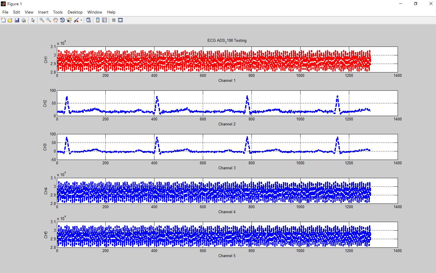
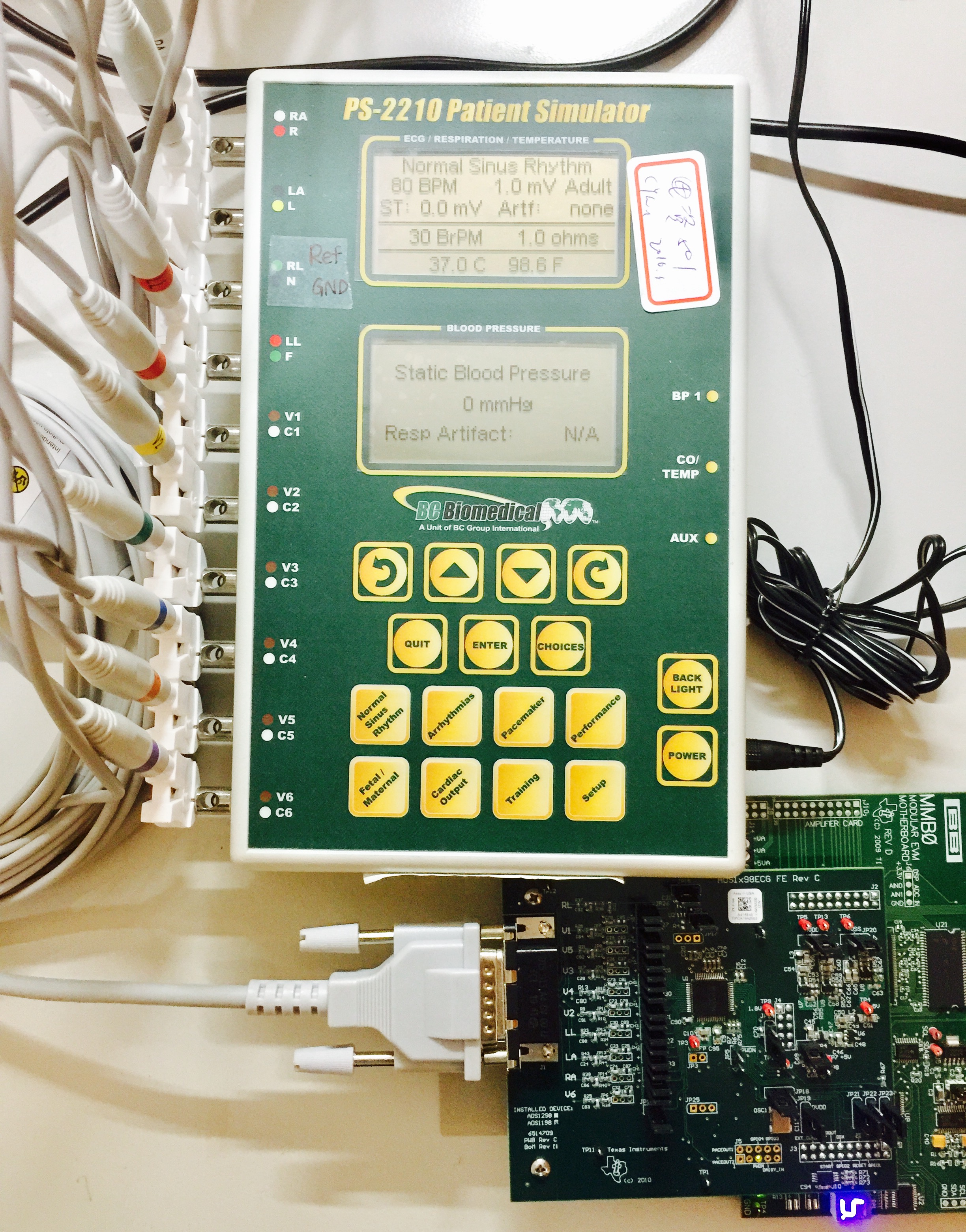
 I have developed bread board with TI ADS 1198 to collect the ECG data, while collecting the data few noise sources are overlapped on the ECG signal, I have observed the signals in MATLAB. I have given power supply through battery of 3.6 V and I have ensured no electrical appliances near by, the connecting wires from Body to board are proper, I wounder how the noise signals are added onto the ECG signal even though I have collected data in noise free environment. 
 
Can one guide me how the noise signals are added on the ECG and I will be thank full if you could suggest better filters to remove the noise.

Looking to your valuable suggestions, thanks in advance.

  • Hello Pratik,

    It is very common for mains interference to couple into ECG measurement systems through the inputs to the system. This occurs because the human body and the electrodes act as antennae conducting signals from overhead lights, motors, switches, etc.

    The RLD amplifier on the ADS1198 is intended to provide negative feedback for common-mode (or almost common-mode) signals that appear on the patient. This is intended to partially counteract the intererence you are seeing. This application note about Right-Leg Drive should be helpful for your understanding.

    In addition to the RLD feature, it is very common for designers to implement a digital notch filter on their processor to further attenuate noise at certain frequencies.

    Regards,

    Brian Pisani

  • Hi Pratik & Brain:

    I am doing kind same thing, but I met some problem in Matlab. If you can give me some suggestion, very thanks !

    I'm working on an ECG-related project, using the TI ADS1198 with the Arduino. I've had success with writing/reading register by SPI bus (for example get ID Register value 182 for ads1198 & set every input channel to Normal electrode ).

    I want to show channel via serial comport to MATLAB, but I got strange wave form like below picture.

    I just show 5 channel firstly, channel 1,4,5 is odd( but i do make this channel in Normal electrode mode ), channel 2,3 seems correct ?

    but not sure. So it is very confuse me why channel 2,3 seems can get data fine, but other can't.

    Here is setting I write to ads1198 register,

    1. Q:  Am I wrong with this setting ?

    Cuz I not much sure about the function from 0x0D to 0x19, just follow the register map table I saw in TI software for ADS1198 demo kit, it can see all channel wave correct.

    void adsNormalElectrode()
    {
      adc_wreg(0x01, 0x04);  //Config1 //0x04 500SPS
      adc_wreg(0x02, 0x10);  //Config2 //0x10
      adc_wreg(0x03, 0xDC); //Config3 //0xDC
      adc_wreg(0x04, 0x03);  //LOFF     //0x03
      adc_wreg(0x05, 0x00);  //CH1SET//0x00
      adc_wreg(0x06, 0x00);
      adc_wreg(0x07, 0x00);
      adc_wreg(0x08, 0x00);
      adc_wreg(0x09, 0x00);
      adc_wreg(0x0A, 0x00);
      adc_wreg(0x0B, 0x00);
      adc_wreg(0x0C, 0x00);  //CH8SET   //0x00
    
      adc_wreg(0x0D, 0x00);  //RLD_SENSP  //0x00
      adc_wreg(0x0E, 0x00);  //RLD_SENSN  //0x00  
      adc_wreg(0x0F, 0xFF);  //LOFF_SENSP //0xFF
      adc_wreg(0x10, 0x02);  //LOFF_SENSN //0x02
      adc_wreg(0x11, 0x00);  //LOFF_FLIP  //0x00
      adc_wreg(0x12, 0x00);  //LOFF_STATP //0x00
      adc_wreg(0x13, 0x00);  //LOFF_STATN //0x00
      adc_wreg(0x14, 0x00);  //GPIO       //0x00
      adc_wreg(0x15, 0x00);  //PACE       //0x00
      adc_wreg(0x16, 0x00);  //RESP       //0x00
      adc_wreg(0x17, 0x00);  //CONFIG4    //0x00
      adc_wreg(0x18, 0x00);  //WCT1       //0x00
      adc_wreg(0x19, 0x00);  //WCT2       //0x00
    }

    I put ads1198 in RDATAC Mode (0x10), and I check its wave form with Agilent logic analyzer, seems correct

    I am sure I convert every channel 16bits data (in 2's complement binary) to decimal value and plot it in MATLAB. 

    The way I deal with 16 bits data in Matlab

    s=serial('COM9','BaudRate',115200); % setup comport  fopen(s);  % Open comport 
    T1=fread(s,1); //Get channel first  byte
    T2=fread(s,1); //Get channel second byte
    ch_1=T1*256+T2;//make it 16bits
    change2dec=dec2bin(ch_1,16);
    value_ch1 = twos2dec(change2dec);

    Here is way I send every byte after I put ads1198 in RDATAC mode

    int adc_read_data(void) //function to read in 5 channel of data
    {
      int i = 0;
      digitalWrite(slaveSelectPin, LOW);
      //attempt to read in one channel only. 3 bytes of STATUS + 2 bytes of one channel data
      int numSerialBytes = 13;// now just read 5 channel to check
      unsigned char serialBytes[numSerialBytes];  
      for (i = 0; i < numSerialBytes; ++i)
      {
        serialBytes[i] = SPI.transfer(0);
      }
      delayMicroseconds(1);
      digitalWrite(slaveSelectPin, HIGH);
    
      for (i = 3 ; i < numSerialBytes; ++i)
      {
        Serial.write(serialBytes[i]); // send one byte to MATLAB
      }  
    }

    2.Q: When DRDY pin goes low, is its time sometime long or short? Cuz in logic analyzer sometime I saw DRDY pin in low longer but sometime shorter  (may be a issue? just guess)

     And this is environment I used:  ECG Simulator , D15 cable, 60-80BPM, 1mV

    Can one guide me what's problem for me to get data this result? how to fix it ? 

    Looking to your valuable suggestions, thanks in advance.

    Best

    Frank | frank613055@gmail.com