This thread has been locked.

If you have a related question, please click the "Ask a related question" button in the top right corner. The newly created question will be automatically linked to this question.

DAC38J84: Complex multiplier question

Part Number: DAC38J84

I am working on a challenging project where we plan to generate 500 tones roughly spaced 1MHz apart in baseband and then up-convert them using the complex multiplier to some intermediate frequency using the on-board NCOs.  My datarate is going to be 625 MHz with 4x interpolation getting us to a DAC rate of 2500 MHz on the output.  I've been able to do this quite nicely on the eval board.

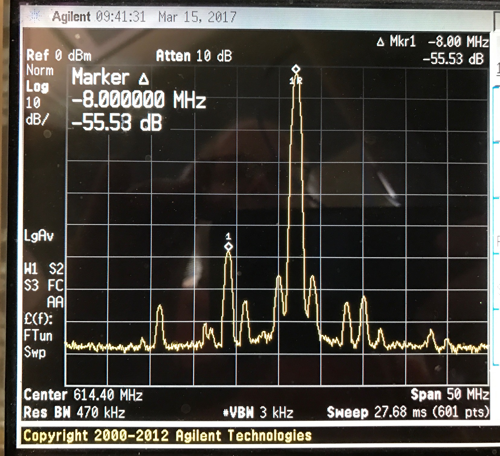
However, we are now checking some results with single tones and noticing some distortion products higher than we'd like (-55 dBc) for single tone up-conversions.  For example, if I have a single sideband at approximately 1 MHz (generated using HSDCpro.  I get some spurious as shown in the attached picture.  

The setup for this case is: coarse mixer at fs/4 using internal clock and internal data rate at 614.4 MHz with a DAC clock of 2457.6 MHz.

I believe this may have something to do with the way the math is done when multiplying two 16 bit numbers while only having a 16 bit output.  I guess my question is this just an inherent problem with trying to use the part in this way, or am I missing some trick?  Thanks in advance,  Dan Van Winkle
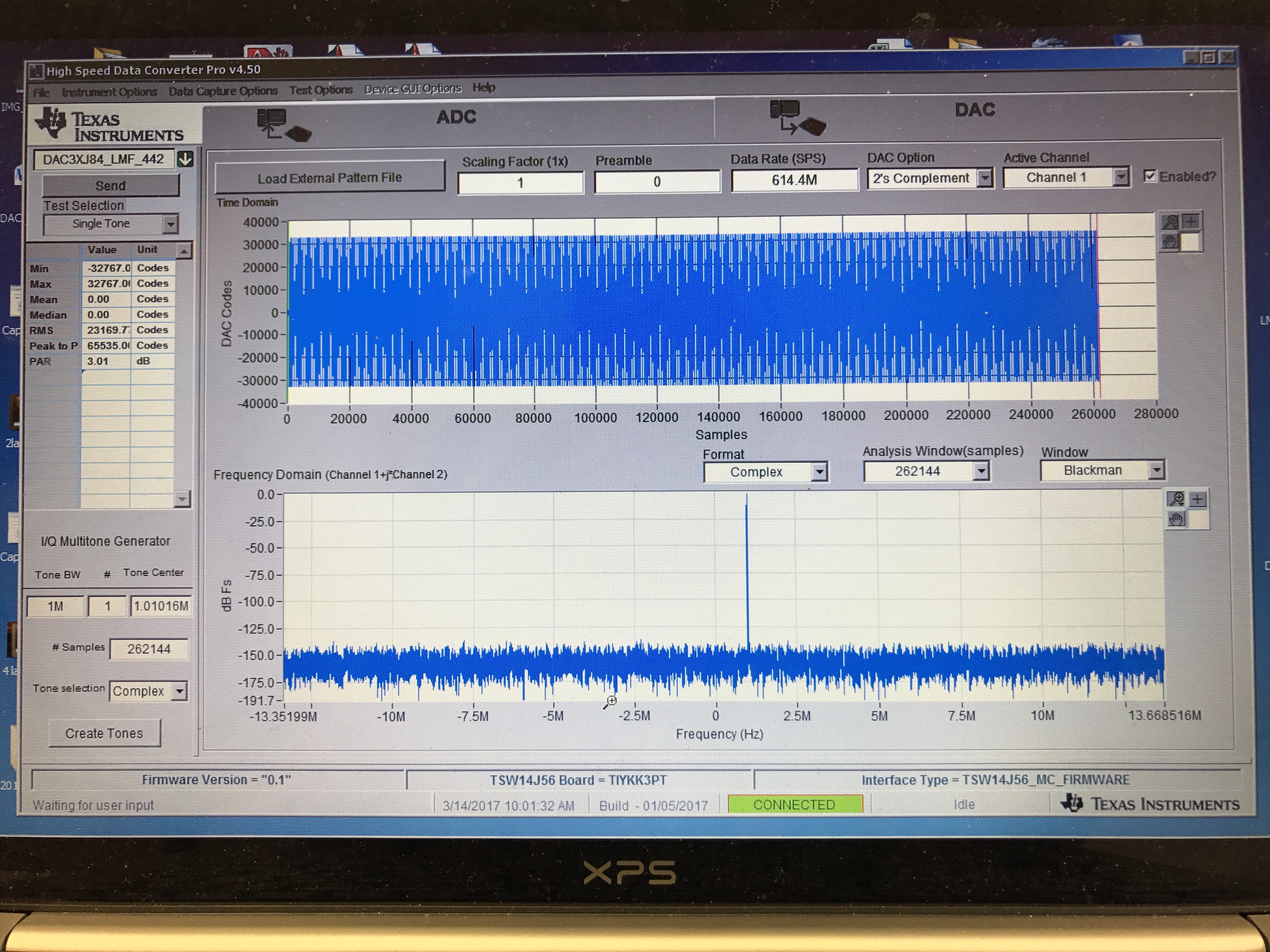
this produces an output spectrum at 614.4 MHz of:

  • Hi Dan,

    When you change the 1R frequency by 100 kHz (ie use 1.1MHz) where does tone at 1 marker go?  I'm trying to see if there is some correlation to a mixing harmonic.

    Also are there other artifacts as you span out (maybe 50M or 100MHz span)?

    Have you tried backing off the signal in HSDC Pro from 1 to 0.707 before sending?  having 2 full scale complex signals into the DAC may saturate the complex math in the complex mixer.  The avg power of a multitone is much lower than a single tone so you may not see this internal saturation with the multitone.

    Let me know if these suggestions help.

    Ken

  • Hi Ken,

    If I move the frequency to 2 MHz, the spur moves to 8 MHz away.  Moving it to 1.1 MHz the spur moves 4.4 MHz away (3.3 MHz below the NCO).

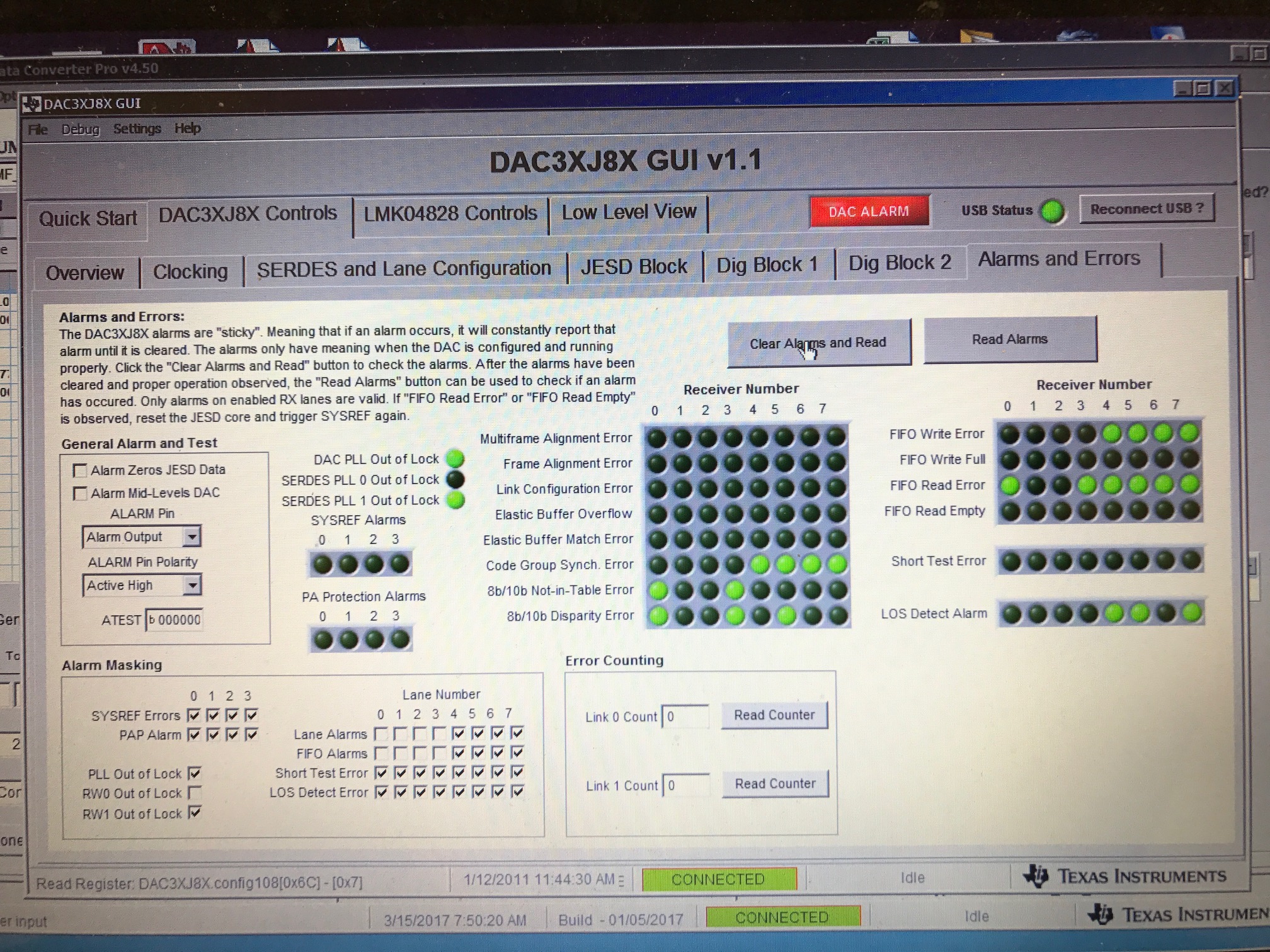
    And, I'm glad you ask about the wider span.  If I ,say, set the frequency offset frequency to something more like 50 MHz, I start to see a very disturbing amount of what look like transient spurious.  If I could attache a movie you could see what I mean.  Instead, I'll attach a couple of shots, one with a fast sweep on the spectrum analyzer and one with a slow sweep.  I do need to understand what these are.  The seem like they might be related to JESD errors since if I go to 8 lanes they do seem to disappear (currently I'm running 4 lanes and see some disparity and not-in-table errors.  The 8 lane case shows no errors (the serdes 8lane rate is a mild 6144 Mbit per lane).  So, it seems as if my eval board may have issues running at the highest rates?

    Also, the 50 MHz offset case shows a spur 400 MHz away so this seems to be a feature of the DAC multiplication.  I would like to understand the mechanism.  The spur seems to not depend on if I change the level of the baseband data (I've gone as low as a scale factor of 0.5.

    The image below is 50 MHz offset multiplied by fs/4 using coarse mixer with 4 lanes (fast spectrum analyzer sweep):

    The image below is 50 MHz offset multiplied by fs/4 using coarse mixer with 4 lanes (slow spectrum analyzer sweep):

    The image below is 50 MHz offset multiplied by fs/4 using coarse mixer with 8 lanes (slow spectrum analyzer sweep):

    Here is a screen shot of the JESD page for the 4 lane setup (the 8 lane setup has no errors:

  • Hi Dan,

    I have a few comments that may help. I think the bit errors are from running the serdes at 12.288Gbps in 4L mode. The TSW14J56 you have is a revB which only supports lane rates up to 10.3Gbps, this was a limit of the FPGA on the revB of the J56. The TSW14J56revD supports lane rates up to 12.8Gbps. .

    The errors at 4L will result in occasional sample errors/glitches. This will look like wideband noise in the base band signal and will be filtered by the interpolation filter to make it look like a hump of noise that is the baseband sampling rate wide. This is exhibited in the 4L 1GHz wide span screen shot (600MHz wide band of noise).

    Can you run the tests in 8L mode to remove the TSW14J56revB and serdes errors from the equation?

    When you say the spur is moving 4x the input frequency, is that away or toward the carrier? Or is that referenced to the Fs/4 mixer frequency? Maybe a screen shot with 1M and 2M input frequency would help me understand more clear whats going on.

    Thanks.
    Ken
  • Hi Ken,  Thanks for your quick response!  Yes, the 8L mode fixes the problem.  I happen to have a revD board that I'll give it a try on so I can rule out the 4L errors (we have to run in 4L mode in our application).  

    I've attached a picture of what happens for a 2MHz signal up-converted by a 614.4 MHz LO using the coarse mixer.  The spurious signal moves away from the carrier.  I'm not particularly excited about all the other spurious, but the big one is a bit annoying...  

    I'll report back about using the revD board.

    Thanks,

    Dan

  • And yes, the revD board runs fine in 4L mode. So that problem is resolved.
  • Dan,

    What you are seeing is the 3rd harmonic distortion folding back along Fs/2.  The typical SFDR performance and HD3 performance is outlined in the datasheet page 15/16.  You can also see this if you use the NCO and sweep the output frequency from 100MHz to 600MHz.

    You will see the HD3 component move up in the Nyquist zone until it hits the Fs/2.  In this case that would be with Fout=409.6MHz, HD3=1.2288GHz.  As you continue to increase the Fout, the HD3 will decrease from Fs/2.

    In your case as you increase the Fout=615.4MHz, the HD3 will be at 3x615.4M=1846.2M

    This will fold back in the 1st Nyquist at Fs/2-(HD3-Fs/2)=1228.8-(1846.2-1228.8)=611.4M

    The level of this HD3 harmonic is not shown on the data sheet for >500MHz output tone, however your measurements of around 55-60dBc seems to be in the expected range.

    If you need better SFDR at this output frequency, you may need to do some frequency planning to avoid the HD3.

    Ken.