Part Number: ADS1198
Hi:
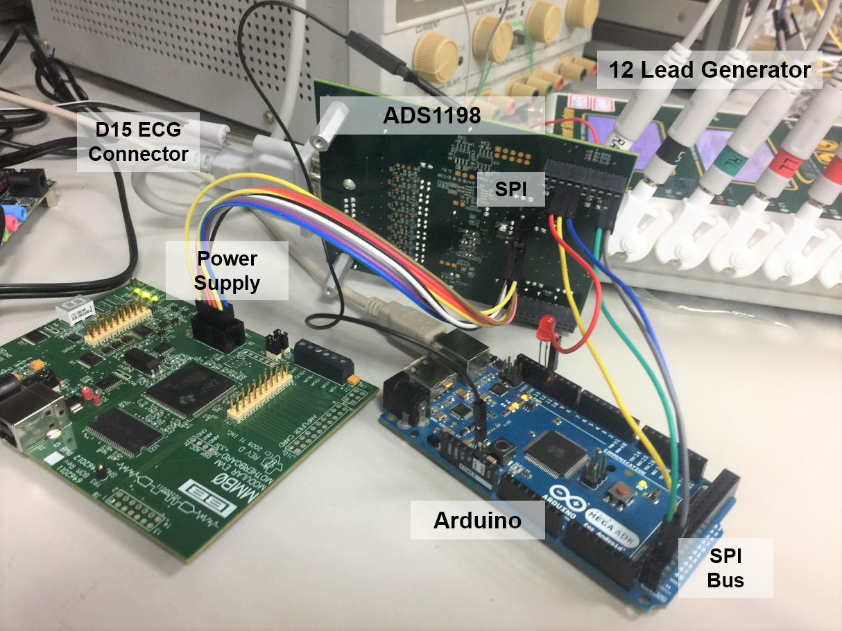
I'm working on an ECG-related project, using the TI ADS1198 with the Arduino. I've had success with writing/reading register by SPI bus (for example get ID Register value 182 for ads1198 & set every input channel to Normal electrode ).
I want to show channel via serial comport to MATLAB, but I got strange wave form like below picture.
I just show 5 channel firstly, channel 1,4,5 is odd( but i do make this channel in Normal electrode mode ), channel 2,3 seems correct ?
but not sure. So it is very confuse me why channel 2,3 seems can get data fine, but other can't.

Here is setting I write to ads1198 register,
1. Q: Am I wrong with this setting ?
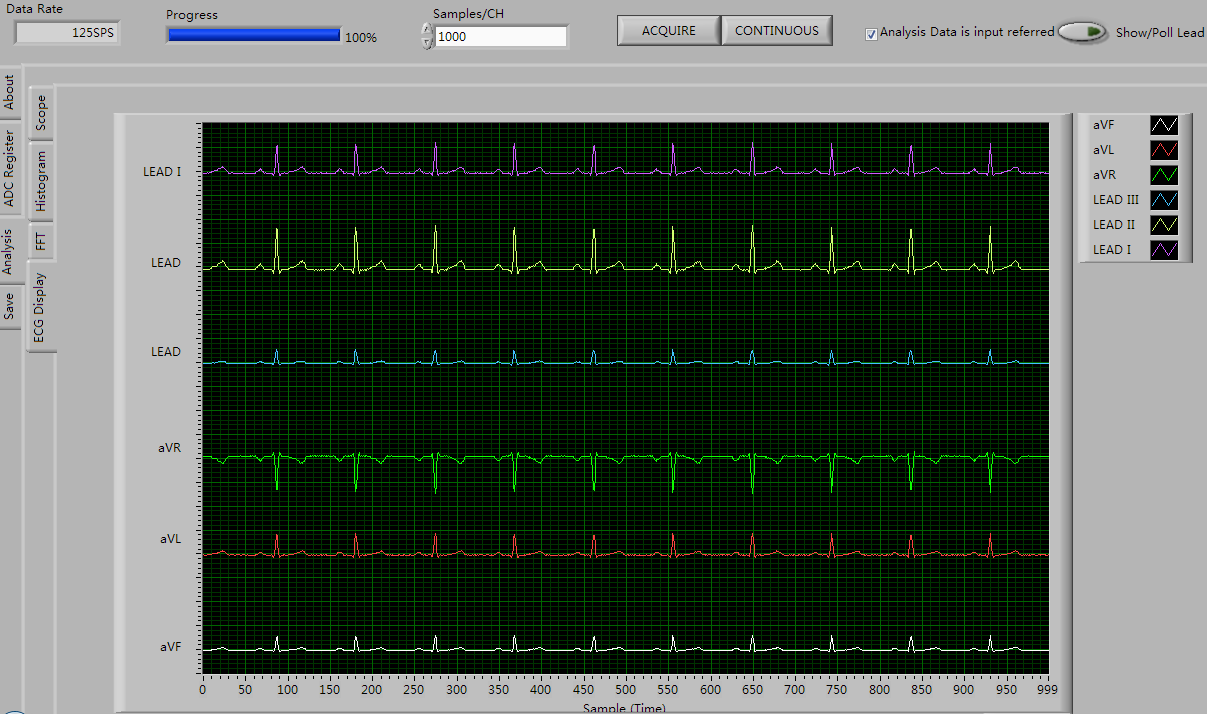
Cuz I not much sure about the function from 0x0D to 0x19, just follow the register map table I saw in TI software for ADS1198 demo kit, it can see all channel wave correct.
void adsNormalElectrode()
{
  adc_wreg(0x01, 0x04);  //Config1 //0x04 500SPS
  adc_wreg(0x02, 0x10);  //Config2 //0x10
  adc_wreg(0x03, 0xDC); //Config3 //0xDC
  adc_wreg(0x04, 0x03);  //LOFF     //0x03
  adc_wreg(0x05, 0x00);  //CH1SET//0x00
  adc_wreg(0x06, 0x00);
  adc_wreg(0x07, 0x00);
  adc_wreg(0x08, 0x00);
  adc_wreg(0x09, 0x00);
  adc_wreg(0x0A, 0x00);
  adc_wreg(0x0B, 0x00);
  adc_wreg(0x0C, 0x00);  //CH8SET   //0x00

  adc_wreg(0x0D, 0x00);  //RLD_SENSP  //0x00
  adc_wreg(0x0E, 0x00);  //RLD_SENSN  //0x00
  adc_wreg(0x0F, 0xFF);  //LOFF_SENSP //0xFF
  adc_wreg(0x10, 0x02);  //LOFF_SENSN //0x02
  adc_wreg(0x11, 0x00);  //LOFF_FLIP  //0x00
  adc_wreg(0x12, 0x00);  //LOFF_STATP //0x00
  adc_wreg(0x13, 0x00);  //LOFF_STATN //0x00
  adc_wreg(0x14, 0x00);  //GPIO       //0x00
  adc_wreg(0x15, 0x00);  //PACE       //0x00
  adc_wreg(0x16, 0x00);  //RESP       //0x00
  adc_wreg(0x17, 0x00);  //CONFIG4    //0x00
  adc_wreg(0x18, 0x00);  //WCT1       //0x00
  adc_wreg(0x19, 0x00);  //WCT2       //0x00
}
I put ads1198 in RDATAC Mode (0x10), and I check its wave form with Agilent logic analyzer, seems correct

I am sure I convert every channel 16bits data (in 2's complement binary) to decimal value and plot it in MATLAB.
The way I deal with 16 bits data in Matlab
s=serial('COM9','BaudRate',115200); % setup comport  fopen(s);  % Open comport
T1=fread(s,1); //Get channel first  byte
T2=fread(s,1); //Get channel second byte
ch_1=T1*256+T2;//make it 16bits
change2dec=dec2bin(ch_1,16);
value_ch1 = twos2dec(change2dec);
Here is way I send every byte after I put ads1198 in RDATAC mode
int adc_read_data(void) //function to read in 5 channel of data
{
  int i = 0;
  digitalWrite(slaveSelectPin, LOW);
  //attempt to read in one channel only. 3 bytes of STATUS + 2 bytes of one channel data
  int numSerialBytes = 13;// now just read 5 channel to check
  unsigned char serialBytes[numSerialBytes];
  for (i = 0; i < numSerialBytes; ++i)
  {
    serialBytes[i] = SPI.transfer(0);
  }
  delayMicroseconds(1);
  digitalWrite(slaveSelectPin, HIGH);

  for (i = 3 ; i < numSerialBytes; ++i)
  {
	Serial.write(serialBytes[i]); //send byte to MATLAB
  }
}
2.Q: When DRDY pin goes low, is its time sometime long or short? Cuz in logic analyzer sometime I saw DRDY pin in low longer but sometime shorter (may be a issue? just guess)

And this is environment I used: ECG Simulator , D15 cable, 60-80BPM, 1mV

Can one guide me what's problem for me to get data this result? how to fix it ?
Looking to your valuable suggestions, thanks in advance.
Best
Frank | frank613055@gmail.com