This thread has been locked.

If you have a related question, please click the "Ask a related question" button in the top right corner. The newly created question will be automatically linked to this question.

ADS5517EVM: Spartan XC3S250E default FPGA code availability

Part Number: ADS5517EVM

Hello,

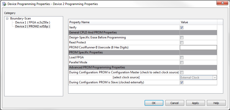
I'm currently using the ADS5517EVM and wish to try modified FPGA code on the onboard Spartan device. I would also like to be able to revert to the original configuration as needed. I believe I would be able to write the custom code to the PROM revision 0 space that is currently inhabited by the ADC CMOS output file and retain the standard LVDS functionality by keeping the original code intact at the end of the PROM, but I would like to avoid this if possible.

Is there any available "original" code for this FPGA?

Thanks!

  • Hi,

    If you have the EVM with the FPGA on it, then yes you would be able to reprogram the FPGA to do what you want it to do but you would be on your own for that endeavor.   If you run into trouble and wish to revert the prom programming back to the original then we may be able to provide the bit file image that was used by the assembly shop to put into the prom at the time of manufacture.   This is a pretty old EVM.  Some years back I inquired for the source code for the FPGA internally and what I was told was that this firmware was not written in Verilog or VHDL.  Back then the FPGA design was done in a schematic capture of Xilinx cells and the FPGA tools compiled the bit file from the schematics.   There was very little actually put into the FPGA at the time so it was a very simple design.   We would not be able to provide the source code, but we should be able to provide the programming file for the prom.

    The ADC was one of our earliest with LVDS outputs and at the time our FPGA based capture card was the old TSW1100 with single ended CMOS inputs, so the FPGA did nothing more that latch in the DDR LVDS and output single ended CMOS.   That allowed the ADC with LVDS outputs to connect to the TSW1100.  Since that time, newer ADCs with LVDS outputs went to a different connector that would connect with our TSW1200 capture card and now the newer TSW1400 capture card. Also, the newer ADS61xx family of ADCs were made to be pin compatible with the older ADS55xx family so the ADS55xx devices could be used on the newer EVMs. Now when the ADS55xx EVMs come up for rebuild for restocking the ADS55xx family of EVMs might be replaced by EVMs that do not have the FPGA at all.  That is why the web page for the ADS5517 EVM has two User Guides available on the page, one for the older EVM with the FPGA and one for the newer version without the FPGA.  Do you actually have in hand the older EVM already?  I just want to make sure you aren't just looking at the User Guide for the older EVM and assuming you will get the one with the FPGA. 

    Regards,

    Richard P.

  • Thanks, Richard. I am currently working with the EVM (REV_B) and it has the Xilinx Spartan FPGA onboard. It's working fine in LVDS mode and I just wanted to try out some other ideas on how to handle the ADC data in addition to the LVDS -> CMOS "buffer".

    I will get in touch at a later time if I need to obtain the programming file you mentioned...
  • Hi Richard,

    Could you please provide me with the FPGA programming file for the ADS5517 EVM (Spartan-3E FPGA) that you mentioned in your original reply? The evaluation module is working fine, but I am unable to revert it to its stock configuration currently.

    Thanks!
  • Hi,

    please see attached the .mcs file that was used by the programming pod software to flash the eeprom for the EVM.  Below is the section from the original manufacture and test document for programming that eeprom for the FPGA.   In the years since, the Xilinx software for the impact programmer has changed so you may need to adapt somewhat.

    Regards,

    Richard P.

    Confirming jumper locations

    1. Confirm JP2 has a jumper set to short position 1-2

    2. Confirm position #8 of SW1 is set to ON while all others are OFF.


      Program the EVM

    1. Apply power 3.3V to J15, J17 and 5V to J14. Set the power supply current limit to 500mA. With no clock on the EVM, the 3.3V power supply current readout should be approximately 30mA.

    2. Connect the Xilinx Parallel Cable VI to JP1 on the EVM, verify the cable’s LED turns green.

    3. Open up the Xilinx Impact program. If the shortcut can’t be found you can run it from C:\Xilinx\bin\nt\impact.exe

    4. Cancel out of the Load File prompt at program startup.

    5. Select “Initialize Chain” from the File menu.

    6. At this point two devices should show up, the xc3s500e and the xcf16p and a dialog prompt will ask you which file to associate with the xc3s500e. Select no file and click on the “Bypass” button.

    7. A second dialog prompt will ask you which file to associate with the xcf16p, select V:\ADS5545\EVM_Software\250E\MBT\MBT.mcs

    8. Right click on the xcf16p device and select Program and confirm the selections made in the figure below. When done, click OK and the device will take about 93 seconds to program.

    9. When the program says, “Programming Succeeded”, power off the board and power it back on. If done correctly, LED D3 and D4 should be illuminated upon restart.

     https://e2e.ti.com/cfs-file/__key/communityserver-discussions-components-files/73/MBT.mcs

  • Richard,

    I am able to program the MCS file to the PROM, but after powering off/on, the D3 LED flashes rapidly and the D4 (DONE) LED never lights.

    In step 8 of your instructions it mentions "select Program and confirm the selections made in the figure below". I think this is the missing link. Do you have this figure or a list of settings for the PROM "Programming Properties" (example from my PC attached)? I think I am just selecting incorrect programming criteria that won't allow the FPGA to be programmed.

  • Hi,

    There was a screenshot in the test document that did not come through in copying and pasting into the posting.  I am attaching the document itself.   Also, back then we had a batch file that we would run that would handle the Xilinx JTAG programming pod commands.  The batch file itself had nothing more than a line to run the Xilinx impact programming code with instructions listed in a file called xlnx_prog.cmd.   The batch file has:    "impact -batch xlnx_prog.cmd pause"    The cmd file is attached.

    Perhaps in this documentation you can find what you need.  It has been a few years since I had run similar tools to program a different EVM, but at that time the Xilinx programming tools had already changed enough that I had to account for different pathnames for where Xilinx installs the tools, etc.   That is why I said you might need to adapt the information as necessary.

    Regards,

    Richard P.

    ADS5545-46 EVM programming and testing procedure.doc

    https://e2e.ti.com/cfs-file/__key/communityserver-discussions-components-files/73/xlnx_5F00_prog.cmd