This thread has been locked.

If you have a related question, please click the "Ask a related question" button in the top right corner. The newly created question will be automatically linked to this question.

ADS1018: The output data is ZERO

Part Number: ADS1018


 Hi  Experts:

                 I am debugging the ADS1018 for my responsible customer,  there is no conversed data output from the DOUT

Power supply: 5.5V 

Input signal:  DC 4.5V

Hardware Configure:  DC input AIN0 ,  AIN1/AIN2/AIN3 floating

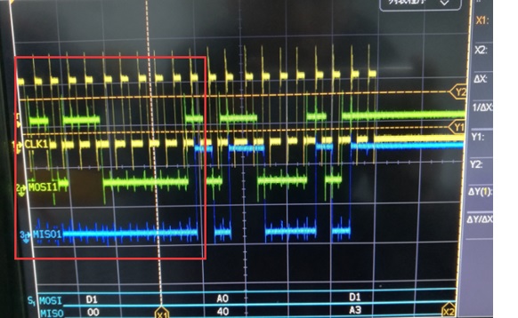
Software Configure: Sending  0xC0CBC0CB   ( Using the 32-bits data transmission cycle with config register readback, please check below waveform , the fist half of the 32 bits are data (ZERO) , the second half is the readback configured register setting ).

  • Hi Jason,

    The conversion result will show zero after power up as the ADS1018 is in single-shot mode and powered down by default.  After the next conversion has completed you should see valid results.  See the first paragraph in section 8.6.1 on page 19 of the ADS1018 datasheet.

    Best regards,

    Bob B

  • Hi  Bob:

              This issue didn't happen only once after power up , they used the continuous mode for reading and the readback data is always Zero, the data slot of the every frame is zero. I also attached their schematic below for your check. For the evaluation , the input is the DC voltage 4.8V on the diode D48. Could you please check the schematic and the register setting I wrote before for the root cause ?

    ADS1018工作原理图.pdf

  • Hi Jason,

    I think the problem is with the communication.  The ADS1018 reads data on the falling edge of SCLK, so the phase is incorrect on the MOSI line.  This should transition on the rising edge and hold stable on the falling edge.  See the Figure 1 timing diagram on page8 of the ADS1018 datasheet.

    Best regards,

    Bob B

  • Hi Bob:

    Yes, it seems the data of register setting on the DIN (MOSI) is out of phase with the SCLK, I will ask customer to reverse the SCLK and check the result . Thanks!
  • Hi Bob:

    Thanks for your comments, customer can get the data right now .

    BTW, for the FSR setting , on the bottom of the page 20, it indicated that the FSR is the full-range of the ADC scaling , do not apply more than VDD+0.3V to device, does it mean that the FSR setting can not higher than the VDD supply ? For example, if VDD is 5.5V, the FSR can not be set to +/-6.144V?
  • Hi Jason,

    The FSR setting determines the value of one code (LSB).  So you can use the +/- 6.144V setting with 5.5V VDD, but you can only apply an input of a maximum of 5.8V (VDD+0.3V) to the ADS1018.  In other words you can use an FSR larger than the supply, but you cannot measure the full range and are limited by the supply voltage.

    I realize this is a bit confusing as most ADCs have a specific reference voltage used in the calculation of the full-scale range.  This device family works a bit differently in that predetermined scaling was used to allow for FSR greater than the supply to be able to measure up to the supply.  Another example would be to use a VDD of 3.3V (a common voltage) but the higher voltage scaling only allows for +/- 2.048, +/- 4.096 V or +/- 6.144V.  If you wanted to measure through the range of the supply, +/- 2.048 would not allow measurement of voltages greater than 2.048 V.  The other two FSRs would work, but you lose more dynamic range by using +/- 6.144V.  +/- 4.096 V allows for the best resolution and allows measurement throughout the range of the supply.  However, you are still limited on the input voltage staying within VDD + 0.3V. 

    Best regards,

    Bob B