This thread has been locked.

If you have a related question, please click the "Ask a related question" button in the top right corner. The newly created question will be automatically linked to this question.

ADS1298: ADS1298 usage problems

Part Number: ADS1298

Hi, i have some questions about the ADS1298 usage problems, First: in the ADS1298 datasheet page1 , what is the " Programmable Gain: 1, 2, 3, 4, 6, 8, or 12" mean? As we know, the ECG signal is less than 5mv , is it mean that the ADS1298 will capture the 5mv signal if we set the gain=1?
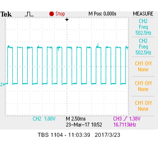
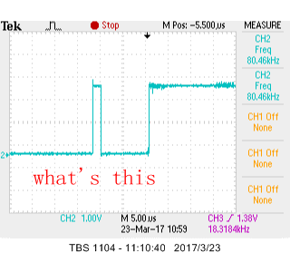
Second: when I set the config 1 to (00 000 100), the output rate is set to 1KSPS, but the actual data rate is 500SPS, when i set the output rate to 500SPS, the actual rate is 250SPS , why?

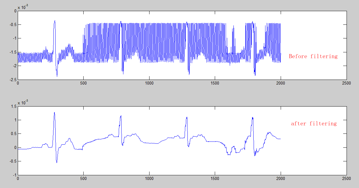
Third: I set the gain to 2, i capture the ECG signal ,  and find the  signal is cut- off and the Amplitude of R-Wave can not be exact estimated ,  it is seen in  the following graph,the signal is cut-off from the second R-wave ,why?

  • Hello Wang,

    Yes you are correct. The ADS1298 features a programmable gain amplifier that can be configured to provide the gains listed in the datasheet.

    How do you know the data rate is half what you have configured it to be? Have you looked at DRDY on an oscilloscope or logic analyzer to validate your theory? If so, take a screenshot and post it here.

    There tends to be a lot of mains interference in ECG applications. It looks like you are seeing some of that in your data. This is commonly addressed through the use of the integrated RLD amplifier on the ADS1298 as well as digital notch filters implemented on the host. You can find more information about the RLD amplifier in the datasheet and in this app note about it.

    Regards,

    Brian Pisani

  • Hi,Brian:

    Firstly thanks tor your friendly help, for the second problem we describe last time , a  Tektronix oscilloscope TBS1104 is used to observe the SPI signal from ADS1298. You can see four -path signals in the following picture 

    channel 1 is clock signal ,channel 2 is DRDY signal,channel 3 is DOUT signal and channel 4 is DIN signal ,

    Zoom in this picture and observe the DRDY signal, we get a photo like this, and we can find that the frequency is 500HZ( when we set the frequency is 1khz) 

    After  we continue to  enlarge this picture , we get the following photo,AS seen there is a  small ***  before each DRDY signal, the cycle is about 10us, what's this ? 

  • Wang,

    The last image is showing DRDY when a sample is not read. As you know, DRDY transitions from high to low when new data is available, and when data is read, DRDY transitions back high at the first falling edge of SCLK. However, when data is not read, DRDY transitions low and stays low until right before data is ready again. Then it briefly comes high and then goes low in accordance with the datasheet.

    Given this behavior and seeing your last image, I believe you are actually missing every other sample. So you are reading data at 500 SPS but DRDY is making a high to low transition at 1 kHz. To validate this theory, track the DRDY signal on the scope again, except this time, do not read any data. You should see positive pulses roughly every millisecond.

    Regards,
    Brian Pisani
  • Brian:

    About the sampling rate problem,you are correct, we modify the program and get the right result , we bought ADS1298ECG-FE and all experiments are finished in the demo board , the default  power-supply for the  ADS1298ECG-FE is a biploar analog supply of +/- 2.5V , now we  use +3V/0  analog supply  , as i understand , in the following graph ,R59-R66 must be installed , but strangely we don't install these resistances and it seems like the circuit works fine and we get the right result and on the contrary, we got nothing if we installed these components ? 

  • Wang,

    Those components are not necessary. You can omit them.

    Brian
  • Hi, it's me again, we used the ADS1298 to capture ECG signal and found it worked  unstabitily, because we make the PCB ourselves, and our drive code is verification in the  ADS1X98ECG-FE Rev ,so we doubt something is wrong in our PCB. In the ADS1298ECG-FE user's guide ,on page 48, figure 39, the pin

    24(VREFP) and pin28(VCAP1) ,the PCB route is widen used the metal-clad, is it necessary? is the current though these pin large and we have to broaden the 

    PCB trace wide? 

  • Hello Wang,

    It is not absolutely necessary to have the trace that thick. There should be very little DC current flowing through either pin. Those pins are mainly for decoupling.

    However, I do not think you should see any problems because the traces there are thick. It will not affect the measurement. What issues are you seeing?

    Brian
  • Hi, my issue is: I made several PCBs and used MCU to get the ECG data, it is strange that each PCB's situation is not same , some work normal at the beginning, i can see the ECG waveform on our own UI screen,and after several (may be in one minute) the waveform disappeared and the ADS1298 didn't transform the data,some didn't work at all ,by the way ,these PCB is not my first batch PCB , I used to make a group of pcb which can work stably for a long time ,the difference between the two group PCB is : 1. the new pcbs i used internal clock instead of external clock (used in the first group pcbs) because i feel the external crystal is too big 2.some trace i don't widen like i did in the old one (as i described yesterday ) . I can find any other reasons except these two difference .

    There is other question i want to ask is i have tested the normal PCBs for some time and i found that  occasionally some abnormal signal would be appeared on our UI screen like the below picture, i asked the similar question in march ,you answer me at the that time is that  use the integrated RLD amplifier to improve the

    common-Mode Rejection . I want to know is it  strongly necessary and effective to add a Drive Amplifier to aviod this problem ? because our company want develop a ECG holter which can record the patients ECG signals in real-time and meanwhile the product must be portable or wearable ,add one component means add  cost , volume and power consumption. 

  • Hello Wang,

    When you say it stops working, what about the device stops working? Does DRDY stop asserting at the data rate? Can you no longer read from registers?

    Also the CMRR issue is greatly improved when using RLD. CMRR is not the only reason to use RL, either. That amp also serves to bias the patient. Without it, you would need to ac couple the inputs which will create more impedance mismatch further degrading CMRR. It is possible to do without the RL electrode, but my opinion is that it is better to include it.

    Brian
  • yes, the DRDY stop asserting at the data rate,  i can't read data from the registers? Can you tell me what you think this  may be related to?  internal oscillator or i left unused pin float?

  • Hi, Brian. The ADS1298 didn't work is our own problem, we already resolved it ,thank you!
  • HI,Brian: The ADS1298 stop work again! and i can no longer read data from its' registers, include the device ID,I solder several PCB, some can't work at the beginning, some works several  minutes and stop work  what's wrong with it ? 

     The following picture is the schematic diagram ,thank you!

  • Hell Wang,

    When the device stops working, please probe the following voltages. All of the voltages are reported with respect to AVSS (i.e. measure them using AVSS as negative voltage). I also put their ideal values so you can see if they are working correctly:

    VCAP1: 1.2 V
    VCAP2: (AVDD + AVSS)/2
    VCAP3: AVDD + 1.9 V
    VCAP4: (VREFP - VREFN)/2
    VREFP: 2.4 V

    Regards,
    Brian
  • Hi,Brian:

    I lay out a new PCB and found that the system current will increase as the time goes on when the MCU let the ADS1298 gathers the data continuous, if i let the system run for a period of time at this situation , i use multimeter to measure the resistance between the VCC and GND ,the resistance will be very small ,even 0 Ohm , and if i I put it aside and don't use it for some time ,the resistance between the VCC and GND will be back to  infinity . so i doubt  that when the ADS1298 get the data continuous, charge in the signal line will accumulate ,so  what's the  request about the ADS1298's signal  line path and the split ground plane or power plane ?

  • Hey wang,

    Can you measure the AVDD current to see if it is larger that the datasheet specification? This can be done if a very small shunt resistor is placed in series with AVDD and you measure the voltage across the resistor.

    Brian
  • Hello, Brian: On the page 36 of"ADS1298ECG-FE/ADS1198ECG-FE user guide " , 4.7 , it is said that"The bandwidth
    of the RLD loop is determined by R8 (392kΩ) and C20 (10nF). Users can change these values to set the
    bandwidth based on their specific application" what is that mean? how i calculate the bandwidth using the value of the R and C?
  • Hello Wang,

    You can use the formula 1/(2*pi*R*C) for the bandwidth of the amplifier. After that point, the magnitude will decrease at 20 dB per decade.

    Brian