Hi,
I am testing ADS5404 operation on a custom PCB at 500MSPS. I am using a 4MHz test CW signal to drive a single data converter channel.
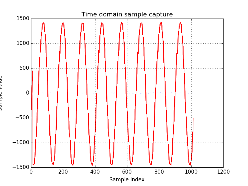
I have enabled DC correction to remove the spurs at DC and Fs/2 as mentioned on page 23 of the datasheet. I have also enabled auto correction which I understand is supposed to reduce the Fs/2 - Fin spur to around 80dbc, however in my case it is consistently at ~42dbc. I have attached time and frequency domain plots of the ADC data.
I have also run the test with auto correction disabled. The resulting plots are indistinguishable.
I have read back the values of the ADC registers during operation, listed below. Are there any known usage conditions or implementation details which could cause the autocorrection to have no effect?
addr: 0x0 value: 0x8000
addr: 0x1 value: 0x8202
addr: 0x2 value: 0x780
addr: 0x3 value: 0xb18
addr: 0xe value: 0x0
addr: 0xf value: 0x0
addr: 0x1a value: 0xb18
addr: 0x2b value: 0x4b
addr: 0x2c value: 0x0
addr: 0x37 value: 0x0
addr: 0x38 value: 0xffdf
addr: 0x3a value: 0x481b
addr: 0x66 value: 0xfff
addr: 0x67 value: 0xfff