This thread has been locked.

If you have a related question, please click the "Ask a related question" button in the top right corner. The newly created question will be automatically linked to this question.

ADS1293EVM: SPI hardware/threshold problem or something?

Part Number: ADS1293EVM
Other Parts Discussed in Thread: CC1310, ADS1293

Hey guys,

I've made a couple of posts about using this, and with your help I got it to work... The thing is that today I hooked everything up, and I wasn't getting any response AGAIN... Looked for the common mistakes (GNDs, powering, etc.), but nothing seems to be off.

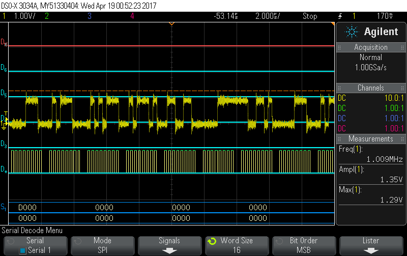
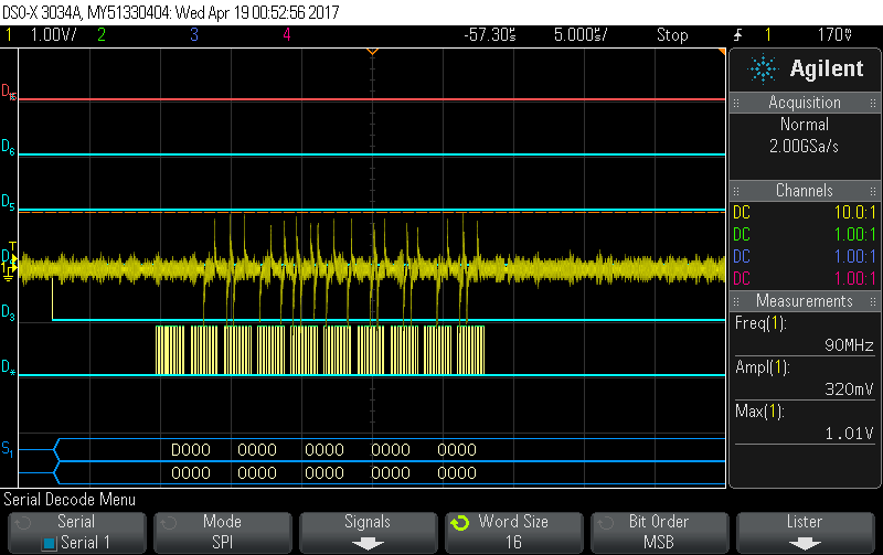
Turned on the oscilloscope to check every single step of the way from the ADS1293 towards the CC1310 Launchpad that I'm using, and found out that the ADS1293 is truly listening to the right values I'm sending from the CC1310 as it is answering back correctly, but only at literally the output probe of the package. (neither the EVM's SDO pin nor the CC1310 MISO pin get any data out of it; they stay at 400mV.)

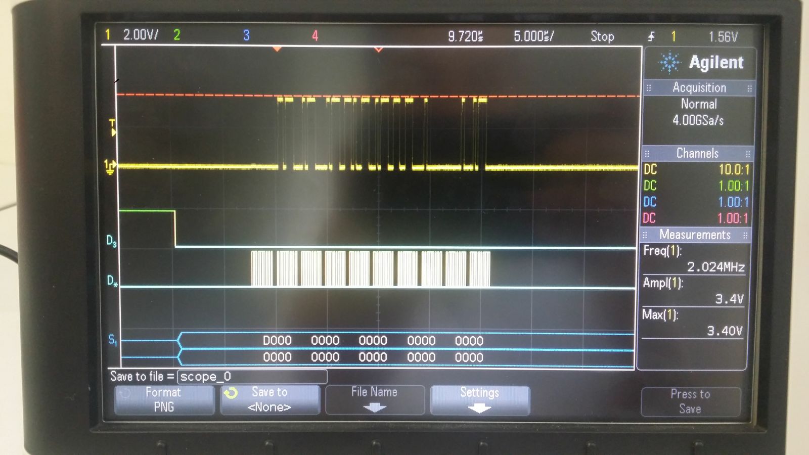
Photo of the probed output:

Here are the photos I took: 

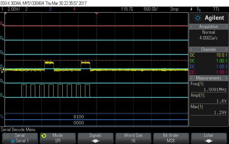
Value requested on register 0x01 -> 0x11 (It is correct...)

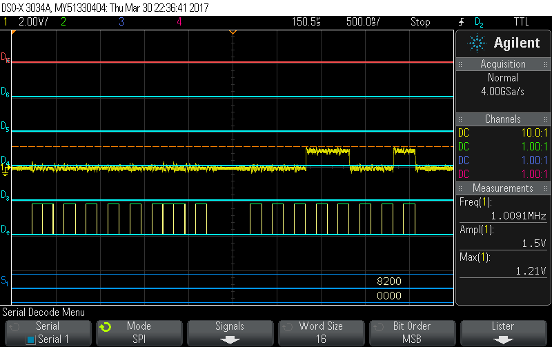
Value requested on register 0x02 -> 0x19 (It is correct...)

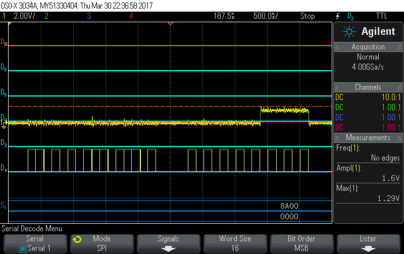
Value requested on register 0x0A -> 0x07 (It is correct...)

After looking at them carefully and calculating what the ADS1293 was answering I noticed that the maximum values were at 1.29ish Volts. (If I can remember correctly, the TTL voltage value's thresholds are 1.4V) So maybe it wasn't getting powered correctly. Thus, I looked for the Vdd Pin to check the Analog Power Supply, and it was at 3.7V. (It is getting powered as should I believe...)

I really don't know what to do, I've tried everything, and it was working a few days ago... Could this be a hardware problem? I tried checking if I get any data on the CC1310, and no... I don't get anything.

Any suggestions of what is happening?

Thanks, Alan.

Edit: 

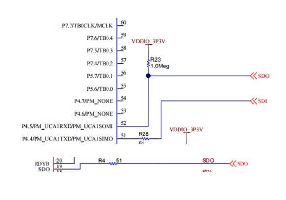
Here's a link to the used datasheet for the pin references on probes: 

  • Hey Alan,

    What is all connected to the SDO pin? It could be that there is something drawing current from the pin and the output buffer on the ADS1293 cannot source enough current. Ensure that the connection to the microprocessor is high impedance. You can actually measure the current by probing across R4.

    Brian
  • Hi Brian,

    Sorry or taking so long to answer, I've been trying everything out before asking for your help again. I tried probing across R4, and this waveform appears... I'm sending different packages continuously so that I can see if there is any answer to any of them at the SDO pin. As I said earlier I am getting an answer immediately at the ADS1293 package SDO pin, but not after R4, absolutely nothing shows up there. 

    What do you mean about the high impedance part? If you're talking about the high impedance if in idle, I am not getting a high impedance value; I get noise from 30mV to 100mV. 

    Thanks for helping,

    Alan.

  • Hey Alan,

    I think you forgot to send the image of what you get by probing across R4. What I meant by high impedance is that ideally no current should flow out of SDO. SDO should be connected to a high impedance input on the host. If it's connected to something else that is not high impedance, it could be dragging the voltage of SDO down. Probing across R4 would allow you to measure the current (measured voltage/R4 resistance) to see if there is something drawing more than normal current from SDO.

    Regards,
    Brian Pisani
  • Hey Brian, 

    Checking how the EVM is working, I can see that there is a pull-up resistor R23 with the SDO connection of the MSP430 and the ADS1293, this should create known state. The SDO output probe or pin that appears on the EVM is what I'm using to interface with my CC1310. You can probably remember from another thread that I had that working. Weirdly enough it suddenly stopped working, and happened what I explained earlier. 

    Here is the schematic of the part that we're talking about.

    Here's what I'm getting on the SDO package pin of the ADS1293. I think that data is correct, but the output communication voltage isn't working as it should.

    Here's R4's probing result. (literally checking just R4 with the response shown above).

    Here's that same result with a zoom in.

    Checking for maximum voltage readings for R4, I'm getting 1.01V... R4 = 51 ohms, therefore the current value is around 19.8mA. It's not even getting to 20mA.

    Hope that this was what you asked for,

    Thanks, Alan.

  • Alan,

    20 mA seems very high to me. I would expect <1mA if everything were working properly. If you depopulate R4 (disconnect it from the rest of the circuit), what is the voltage that you read at SDO? If my theory is correct, the voltage should be close to VDDIO.

    Brian
  • Hey Brian,
    But by removing R4 there would be no physical connection between the SDO of the EVM and the SDO package PIN of the ADS1293; I would still be measuring just the package's SDO pin data. Should I still try that?
    Greetings, Alan.
  • Alan,

    Yes. By disconnecting the ADS1293 SDO pin from everything else and measuring the logic level, we are attempting to rule out the ADS1293 as the source of the issue.

    Brian
  • Brian,

    I'll try this as soon as I get to the lab and post back my results.

    Thanks, Alan.

  • Hey Brian!

    Well I did what you instructed, and as you can see in the screenshots (or more like photos because I lost my USB, SORRY!), it's answering properly. 

    Photo of the ADS1293 answer to a read register 0x50 with the oscilloscope probe.

    Photo of the answer of the ADS1293 using a logic analyzer.

    Just a summary of the problem and solution:

    The problem was that the MSP430 was still drawing current from that specific PIN and wouldn't let estabilish a normal SPI communication between the CC1310 and the ADS1293.

    By desoldering the resistance R4 (51 ohms) it completely disconnected the ADS1293 SDO package pin from the MSP430 MISO pin; avoiding any further problems from the MSP430 to the ADS1293.

    Anyways, I should probably delete the trace after R4 towards the MSP430 and resolder R4 so that the 51 ohms resistance can electrically protect data transference right? (I don't know If I explained myself lol)

    Thanks a lot, 

    Alan.

  • Alan,

    If you disconnect the MSP430 from the circuit, and re-populate R4, it should work fine.

    Regards,
    Brian