This thread has been locked.

If you have a related question, please click the "Ask a related question" button in the top right corner. The newly created question will be automatically linked to this question.

ADS1299: Problem with using ADS1299 to acquire ECG

Part Number: ADS1299
Other Parts Discussed in Thread: ADS1298ECGFE-PDK

Dear all,

I am trying to use ADS1299 to acquire ECG.

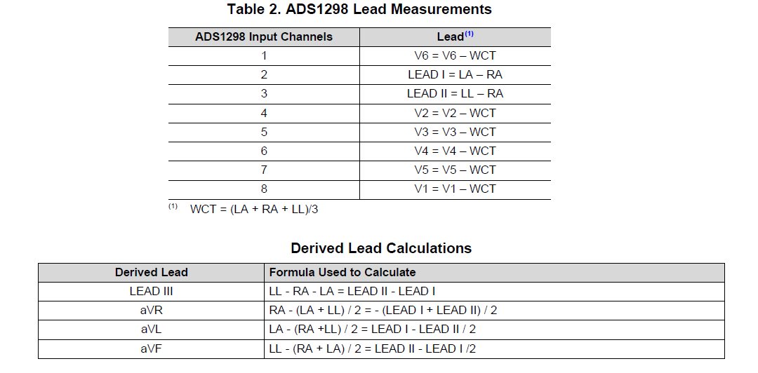
I have already acquired EEG with my own demo board. I also want to acquire ECG data.I use Biasout as Right Leg Drive and set the inputs refer to the datasheet of ADS1298ECGFE-PDK as shown: 

I get WCT from the average value of RA,LA,LL by a opamp adder. And I assign the WCT to BIAS_IN pin as negative input by setting CHxSET = 0x67.V1-V6 is connected to positive input.

But the channel is saturated, the data is 0x7FFFFFF or 0x800000 for V1-V6 while the LEAD I and LEAD II is good.I try to use SRB2 as input for WCT(change V1-V6 to negative input), the result is same.I can not use SRB1 as negative input because SRB1 is connected to every channel when it is set in MISC2. But the LEAD I and LEAD II need RA act as negative input. 

When I connect WCT directly to negative input of the channels, I can get the V1-V6 data.Is there any problem with my settings?

Thanks.

  • Hello user4342371,

    Take a look at Figure 33 in the datasheet. The channel 8 portion diagram shows the connections when the MUXn[2:0] bits are set to 111. Note now the switch connecting the negative input to BIASIN is closed, but the switch connecting to the channel input is open. In this mode, you cannot measure on channel 8. This behavior is only intended for when the RL electrode falls off so you can route the drive signal through a different electrode.

    In the case where you try to measure WCT through SRB2, you can see in Figure 18 that SRB2 actually connects to the positive input. You stated that you also have the electrodes connected to the positive inputs so there is nothing connected to the negative input in this case. What you could do is connect the electrodes to the negative inputs and then just flip the sign of the samples once you receive it on your processor.

    Regards,
    Brian
  • Dear Brian,
    Thank you for your reply.
    You can notice that I mention I switched V1-V6 to negative input when I use SRB2 as WCT.
    This figure 33 in ADS1299 datasheet is DRDY with Data Retrieval (CS = 0). I find Figure 46 which is the same as you described about BIAS_IN function. Because BIAS_IN can not be used for WCT. It seems SRB2 is the only way. I will try it again in a few days.
    Thanks.
  • Hello user4342371,

    Yes I see now that you did say that you switched the inputs. In any case, using SRB2 should work. Perhaps you can validate the setup with a bench signal source to work out any bugs before trying to capture an ECG signal.

    Regards,
    Brian
  • (seeking help form Brain)
    Hi brain,
    I am facing a problem with ads1299 board. Internal test signal (square wave )is fine . But unable to get external signal(ECG ). I tried to acquire ECG via arduino uno and labview.
    Following is the registers setting . I don't know where is the fault.

    ADS.verbose =false;
    ADS.RESET();
    ADS.SDATAC();
    ADS.WREG(CONFIG3,0xE0);

    ADS.WREG(CONFIG1,0x96);
    ADS.WREG(CONFIG2,0xC0);
    ADS.WREG(MISC1,0x20);

    for(byte i=CH1SET; i<=CH8SET; i++)
    {
    ADS.regData[i] = 0x60;
    }

    ADS.WREGS(CH1SET,7);

    ADS.RREGS(0x00,0x17);


    ADS.RDATAC();
    ADS.START();


    Kindly help me in this regard
  • Hello Golam,

    It seems like the bias buffer is disabled in your register settings. You will need to enable this and connect a bias electrode from the output of the bias buffer to the patient like a RL electrode in order to establish a common-mode voltage for the inputs.

    Regards,
    Brian