This thread has been locked.

If you have a related question, please click the "Ask a related question" button in the top right corner. The newly created question will be automatically linked to this question.

ADS1115: Understanding the differential function

Part Number: ADS1115


As a noob when it comes to EE, I need a bit more info on how the Differential function works on the ADS1115.

I understand that I can use the differentiator to calculate the difference between A0 and A1 as well as A2 and A3.

My question is, when using this function, do both A0 and A1 resolve to GND?  

In examples I have seen (maybe not the best examples), I see people measuring a battery using A0 and A1 (with negative on A0 and positive on A1).  This is fine, but then I wonder how it would work with a battery in series (let's say a 2S battery with each cell at 1.2V).   

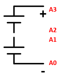
Would that look like the following?

A0 -> Cell 1 negative   (0 V -> same as GND)
A1 -> Cell 1 positive    (1.2V)

A2 -> Cell 2 negative   (0V or 1.2V?)
A3 -> Cell 2 positive    (1.2V or 2.4V?)

As they are in series, cell 1 positive is the same terminal/wire as cell 2 negative.  Does this mean that A2 voltage is 0V or 1.2V?   Is A3 voltage 1.2 or 2.4V?

Are A0 to A3 all resolving down to GND?

resulting in:
A0: 0V
A1: 1.2V
A2: 1.2V
A3: 2.4V

assuming wired as described.  What would the actual voltages for A0 to A3 be for the following assuming 1.2V for each cell?

  • Jonathan,


    The "differential function" is really a differential measurement. The ADS1115 makes differential measurements with the ADC, so that the ADC reports the voltage of AINP-AINN through the multiplexer as shown in Figure 25. With the differential measurement, you could get a negative value if AINN is higher than AINP.

    In comparision, you could make a single-ended measurement where the AINN is grounded and any other input of the multiplexer would be connected to AINP. All ADC results would be positive with no negative values.

    Going back to your example, if you select A1 as the positive input and A0 as the negative input. You'd measure 1.2V.

    When switch channels, the ADC inputs are then A3 as the positive input and A2 as the negative input. You would also measure 1.2V. Each time, you'd measure the difference between the positive positive input and the negative input.

    The inputs are measured through a multiplexer. They should measure the inputs without affecting the other inputs that are not connected to the ADC at the time.

    Therefore, with the cells stacked and with A2 connected to A1, you would get:
    A0: 0V
    A1: 1.2V
    A2: 1.2V
    A3: 2.4V


    Joseph Wu
  • Thank you Joseph!  That is exactly what I needed to now.

    And to confirm, the voltages at A0 to A3 can never exceed VDD +.3V as they must all still be relative to GND, correct?

    In cases where input voltage is greater than VDD +.3V a voltage divider is the recommended approach?

  • Jonathan,


    As long as the input voltages are between GND-0.3V and VDD+0.3V, you'll be able to make measurements.

    If the input voltage is greater than VDD+0.3V, you could use some sort of voltage divider. However, note that the ADC has a finite differential input impedance as listed in the Electrical Characteristics Table on page 6. If your divider resistors are too high in resistance, you'll see some error because of it.


    Joseph Wu