This thread has been locked.

If you have a related question, please click the "Ask a related question" button in the top right corner. The newly created question will be automatically linked to this question.

ADS42LB69: ADS42LB69 SPI interface issue

Expert 1750 points
Part Number: ADS42LB69
Other Parts Discussed in Thread: SN74LV1T34

Hello,

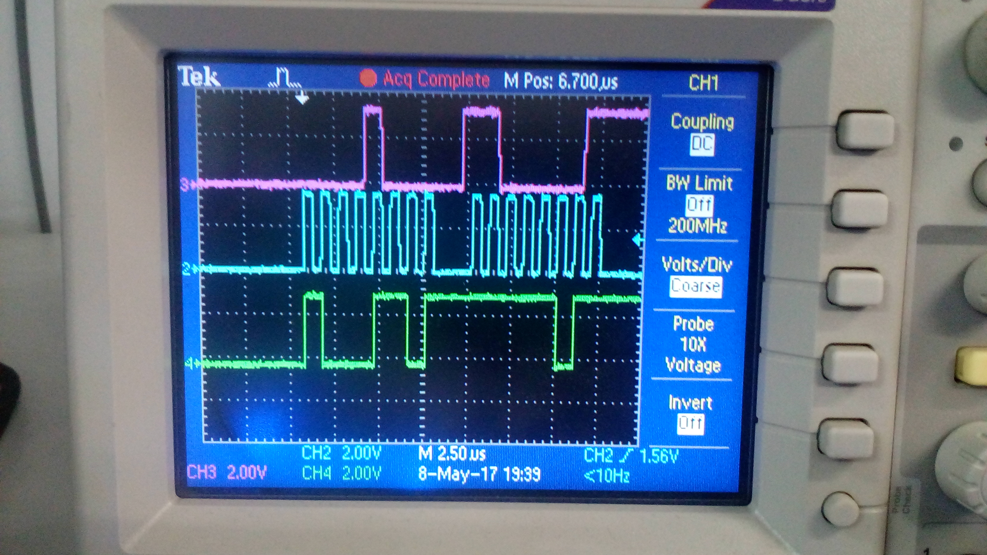
        We are facing an unusual problem with the serial interface of the ADS42LB69. 

1) Every read is returning a different value! We have looked at the waveforms on an oscilloscope and they agree with the values being read. 

2) There is data on SDO (serial data out of the ADS42LB69) even when address is being written to it in write mode. 

It is clear that the data being written on SDO is only from the ADS42LB69 (there is no other device on the SPI bus). We have also tried varying the Serial Clock but it doesn't help. 

Please advise, 

Thank you for your time in helping us out,

  • SM,

    Are you doing either a hardware or software reset after power up? If doing a software reset, do you have the reset pin tied to GND? Is CNTRL1 and CNTRL2 connected to GND? Are you setting the R/W bit to "1" when attempting a read? Can you verify you are doing proper writes by monitoring the current after power up then write to address 0x08 to power down both channels.

    Regards,

    Jim

  • Hello Jim,

               Thank you for your prompt response.

    1) We are doing a software reset

    2) The reset is pulled to GND with a 10K resistor

    3) CNTRL1 & 2 were not connected to GND but are now (after your input), but still the result is the same

    4) No, the power consumption does not drop if the 0xC0 or 0xC1 is written to 0x08 register address

    Attached are screenshots of the writes. (cyan is SCLK, purple is data being written to the ADC and green is the signal at SDO of the ADC). 

    Thank you once again,

  • SM,

    I do not see SEN on the scope shot. Is this low during the write? Can you replace the 10K resistor with a 0 Ohm part?

    Regards,

    Jim

  • Hello Jim,

               Yes, SEN is low during the writes to the ADS. We replaced the 10K with 0E but the problem persists. 

    Your idea that the power consumption should come down when the channels are powered off is great but we are unable to see that. 

    Obviously there is a SPI interface issue.

    In order to experiment, we made SEN high during the writes and there was no response from the ADS, which in our understanding indicates that the connections on the PCB are alright. We are a little puzzled about why the does the ADS write back something even when it only being issued a write command. 

     2) Also there is another issue. The SDO of the ADS is at 1.8V logic level while the rest of the devices on the bus are at 3.3V. We used a SN74LV1T34 to convert this 1.8V logic to 3.3V and it works (the level translation works) but the rest of the devices on the bus are unable to send anything on this bus (it always stays low). Will using a level shifter with a tristate output help? Please suggest a part number. 

    The second problem is  on a separate board where multiple SPI devices are present.

    The problem with SPI communication when only the ADS is on the bus is still there. 

    Please advise,

    Regards,

    Shashank.

  • Shashank,

    Lets get the writes working before worrying about the reads. Does your board allow you to issue a logic high reset pulse on the reset pin after power up? If not, can you make a modification to allow this? Are you always writing a "0" to address A6? After power up, and issuing a reset, if you have a CLK connected to the device, and CNTRL 1 & 2 grounded, you should be drawing current on all supplies. After this, write a 0xC0 to address 0x08. This should cause the power to go down. If you cannot get this to work, there is either a timing issue or the part may be bad. What is the frequency of SCLK? This cannot be greater than 20MHz. If you are reading data back on the SDO lines when you do a write, there may be a chance you issued a read command or some other signal is driving this net. SDO is tri-stated when the ADC is not in read mode. This is the only explanation I can give for this.

    Regards,

    Jim 

  • Hello Jim,

               Yes, I agree we need to get the writes working first.

    1) We will try to solder a wire to do a hard reset.

    2) "Are you always writing a "0" to address A6?"     I think there is a typo (there is no address A6).

    3) Yes, when we supply a clock to the ADC with CTR1,2 grounded (without any reset happening) the current does go up (which I hope indicates that part is working)

    The SPI bus is running at 1MHz. 

    4) Data showing up on SDO even in write mode is something we are unable to explain. 

    We are monitoring the signals on an oscilloscope and we see no read signal being sent (of course we might still be missing something) but we have looked at the signals on the oscilloscope many times to confirm the same (also we have written the SPI controller code ourselves, so we know that nothing else is being sent). 

    5) Is there any requirement on the SCLK line to be high or low when inactive?

    Looking forward to your inputs,

    Regards,

    Shashank.

  • Shashank,

    By keeping A6 low, I was refereeing to Figure 89. This is bit 6 of the address input. SCLK has an internal pull down, so you can either keep this signal low or tri-state it. I would not keep it high. Can you make the SCLK cycle 16 consecutive pulses instead of 8 with a gap in between? I will check with the design team regarding this.

    Does your SEN go high no earlier than 25ns after the 16 SCLK?

    Regards,

    Jim   

  • Jim,
    The addresses we are writing to (especially for the first one, 0x08) are all below d63 (hence A6 will always be 0).
    It will be very difficult for us to modify SCLK to 16 consecutive pulses (we now use built in libraries to implement SPI). Also this approach (i.e., 8 cycles with a gap and then 8 again) works fine for all other ICs that we use, so I really hope this is not a problem.
    Further, SDO starts sending out data even before the end of the first 8 clock cycles (can be seen in the pics I sent earlier), so I don't think this is a problem.
    We just checked, SEN goes high after at least 1 us after the 16SCLKs.

    I think there is something wrong in the way we start because SDO starts throwing out data even during the address write duration. Also, even if we are sending a read command SDO should not become active until the 9th clock cycle.

    Regards,
    Shashank.
  • SM,

    I would try to do the hardware reset next. Is this a problem across multiple systems?

    Jim

  • SM,

    Are you doing the following after power up:

    write 0x01 to add 0x08 to set reset high

    write 0xC0 to add 0x08 to power down both channels

    If you are resetting the part and powering down the channels with one write, this will not work.

    Jim

  • Jim,
    We did the following:
    1) Soldered wire to do a hard reset and gave a 300us reset pulse on power up. The SDO activity has stopped now.
    However the power does not drop when 0xC0 is written to 0x08.

    2) We connected the wire going to the reset pin to ground (on power up). And then applied a soft reset (i.e., wrote 0x01 to 0x08). In this case also the SDO activity is absent but the current does not drop in the 0xC0 case.

    May I ask if it would be possible for you to help us again tomorrow (10th May) around this time. It is 7:30 PM now and our PCB design engineer and the lab technician have left for the day. We will have everyone involved around so that we can resolve the issue.

    Regards,
    Shashank.
  • Jim,
    I think there is some life in the SPI interface now.
    Writing 0xC0 to 0x08 did not drop the current consumption but 0xE0 did!
    Toggling between 0xE0 and 0xC0 is making the current go low and high resp.
    I think you can help us in the normal routine as you have been doing so far (no appointment for tomorrow).
    What could be the reason for the absence in response for 0xC0?
    Thank you very much for your help in working this out,
    Regards,
    Shashank.
  • SM,

    After running our GUI on our EVM I just noticed there needs to be one more bit set to power down the device. Please try writing a 0xC8 to add 0x08 to power down both channels.

    Regards,

    Jim

  • Hello Jim,
    Yes, 0xC8 works.
    We are seeing the following:
    Hard reset works all the time. By works I mean that the SPI interface works and the device responds to the commands being sent.
    Soft reset:
    We tried connecting the reset pin to ground using a 0E and a 10K resistor. In both the cases, the startup is in-consistent. Sometimes, the SPI interface works and sometimes it doesn't.
    In the case it doesn't work the current consumption is slightly higher than when it works (upon power cycling, without reset being done).
    We now have a jumper wire connecting the controller and the reset pin which will work for the protos but cannot be used in our product.
    Please advise and thanks again,
  • SM,

    After you write the software reset, always follow this with a write to add 0x08 with data 0x08. This is what our GUI does and I never see any issues with the soft reset.

    Regards,

    Jim