A related question is a question created from another question. When the related question is created, it will be automatically linked to the original question.
If you have a related question, please click the "Ask a related question" button in the top right corner. The newly created question will be automatically linked to this question.
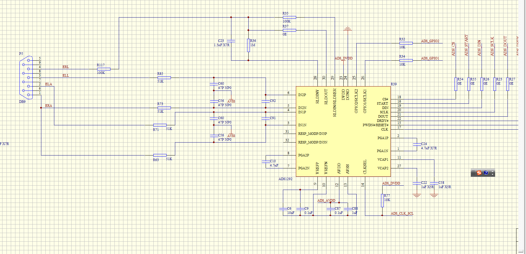
ADS1292: check SCH reference the TI design and simplify
we reference the TI design and simplify, may need your professional support,we need smallest PCB, if you have some idea pls provide for reference, tks~
Maybe remove the resistors in series? Basically you can remove 8 resistors. All the MCUs (as far as I have experience) have all the GPIOs in input configuration (if not disabled) after startup. So if you are careful with coding, removing them wouldn't hurt.
What about R77? If it is always connected to MCU that can be removed too.
And if the AFE always uses internal clock you can remove the CLK connection. It's a somehow high frequency track and in your small design I guess you would prefer not to trace it if it is not needed. Also the connection for START pin can be removed. This can free up a little space on your PCB. I guess the power consumption is also important for you so you should keep the PWDN connection to be able to put the IC in power down.
And one more thing. I noticed that VCAP1 and VCAP2 are connected to digital ground. I guess they should be bypassed with analog ground.
The schematic is almost functionally correct. Pin 13 needs to connect to the negative supply, though. Right now it is floating. Referring to Vala's comments, the VCAP pins should be decoupled to analog ground.
In terms of optimizations, you should keep the series resistors on the inputs for anti-aliasing. The series resistors on the digital I/Os are also unnecessary. Vala is right; there is no need to connect the START pin to the host since you can use the START command to control conversions. Simply tie the START pin to ground. Do you plan on using the internal clock? If so the CLKSEL pin can always be held high and the CLK pin may be left floating. There is no need for resistors on the GPIO pins.
Thanks Brian for clarifying my comment. By the resistors in series I definitely didn't mean the ones in in the analog path. I meant those lines that are connected to MCU.