This thread has been locked.

If you have a related question, please click the "Ask a related question" button in the top right corner. The newly created question will be automatically linked to this question.

ADS1298EVM noise problem

Hello!

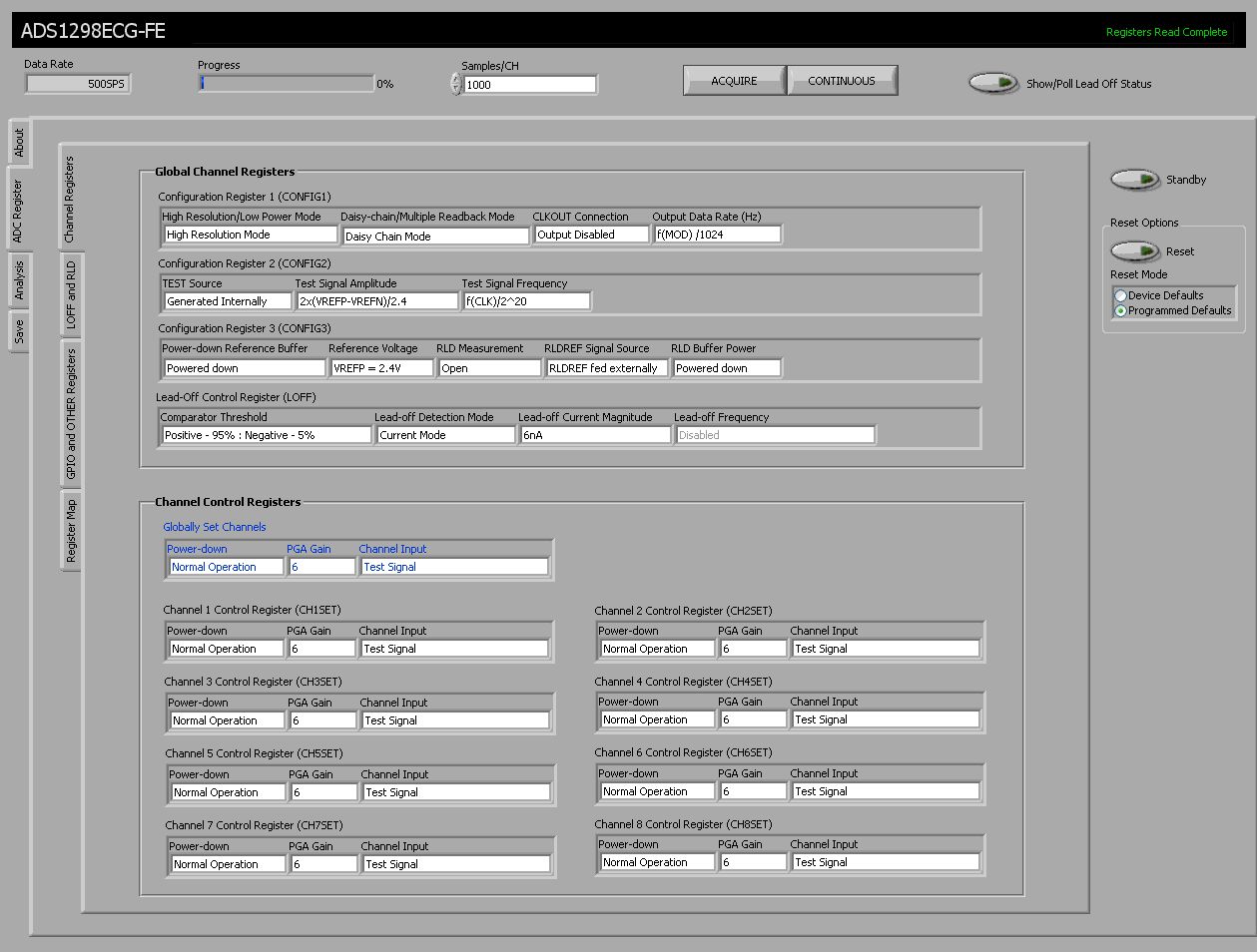
I have a problem with the internal test signal noise of the EVM. There seems to be much more noise in the waveforms as is suggested by the user guide, which doesn´t show any ripple in the signal. I´ll include some screenshots of the analysis tab for a better overview of the problem.
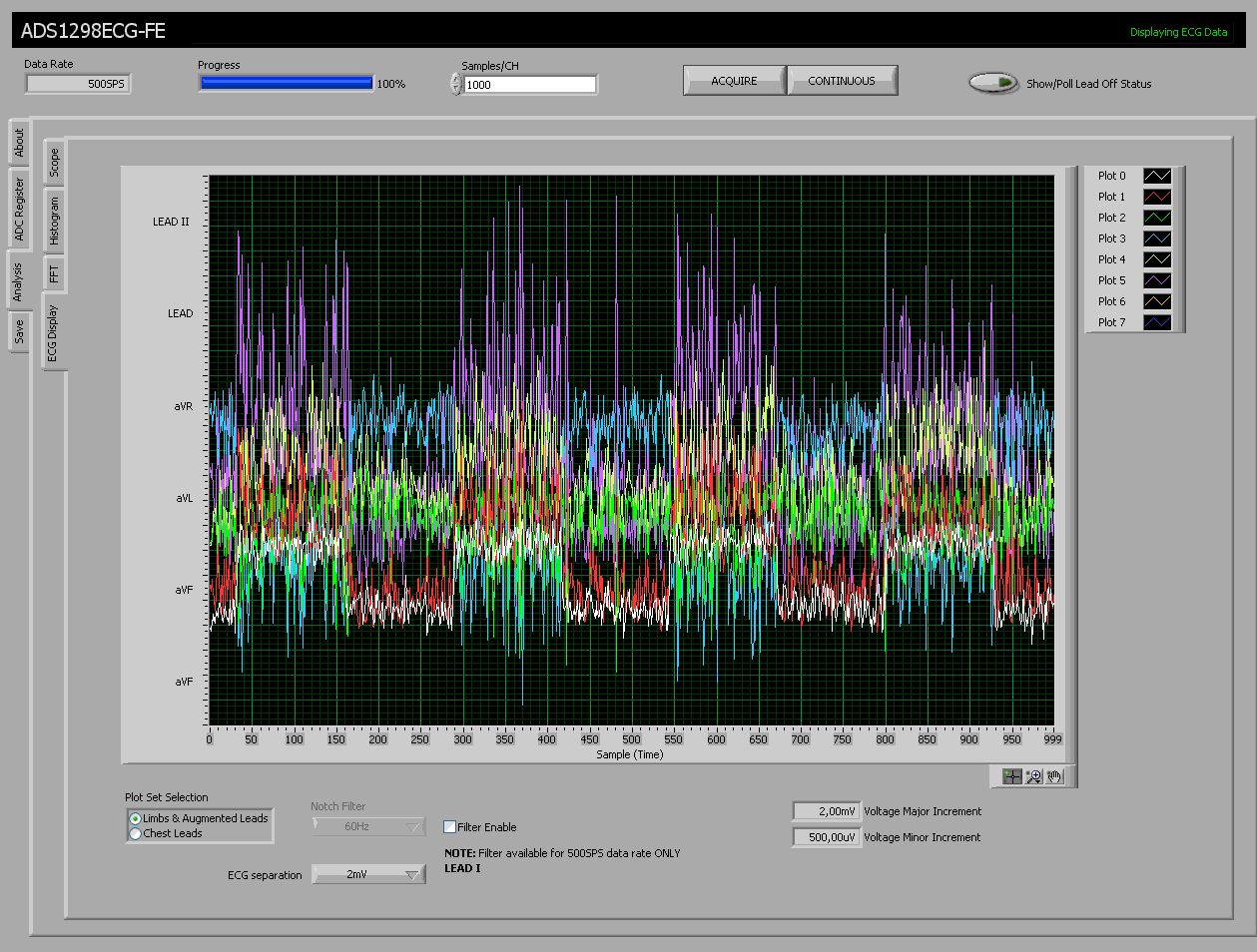

When I change the channel input type to normal input then the signal displayed by the scope tab shows very erratic behaviour and nothing but spikes.

In general it is difficult to get data from the EVM - when hitting the acquire button the software often displays the message "DSP collecting data" and crashes.

I thought maybe there is a connection between the two phenomena.

Any help on finding the cause and a solution to the problem would be much appreciated.


Best regards

Kaarel


  • Hi Kaarel,

    Can you tell me which version of software and firmware you are running?  The SW version is found in the Help, About menu and the FW version is listed on the About tab.

  • Hi Tom,


    Sure, my software version is 0.7.1.2 and firmware version is 0.2.15.


    Best regards

    Kaarel Maearu

  • Thanks Kaarel -

    That's the latest code, so I'm not sure what might be wrong here.  Can you verify that all the jumpers on both the ADS1298EVM and the MMB0 that it is sitting on are in the default positions noted in the Users Guide for me and also check the voltages at the various red test points around the board?

  • Hi Tom,

    I measured the voltages at various test points. Here are the results:

    TP7       +4.99V
    TP10    +3.29V
    TP9      +1.81V
    TP5      +3.01V
    TP13    +2.51V
    TP6       -2.50V
    TP4       -4.99V
    TP3      +0.04V

    I also checked the test points  for ripple with an oscilloscope and found only mV scale noise, nothing more.  The external oscillator signal also looks nice and the frequency is exactly 2.048 MHz.

    I didn´t find the default positions for all the jumpers in the user guide, but I can give you a list about how mine are configured:

    JP19     2-3
    JP1       INTSTALLED
    JP2       2-3
    JP24     1-2
    JP5       NOT INSTALLED
    JP28     2-3
    JP4       INSTALLED
    JP22     2-3
    JP23     1-2
    JP25     1-2
    JP26     2-3
    JP27     1-2

    As I checked my jumpers I noticed that JP2 and JP24 were configured for the board to be in bipolar analog supply mode. I put the board to unipolar analog supply mode and saw some improvements on the test signals, but still, the problem persists. The settings were the same as on the first time.

    http://img339.imageshack.us/img339/8360/ecg2.jpg
    http://img714.imageshack.us/img714/985/scope2o.jpg
    http://img580.imageshack.us/img580/8594/settingsn.jpg

     Another strange fact occured when I changed the board from high resolution mode to low power mode - channel 1 now displays a square signal(before it had just noise) while other channels just show more noise. Channel 8 seems to have the highest fidelity regardless of the settings.

    http://img202.imageshack.us/img202/8382/scope2lowpower.jpg

    The 8-segment display shows an arbitrary character. Is that normal?

    http://img230.imageshack.us/img230/4849/img4090a.jpg

    If you need some more measurements just let me know.

    Hope this helps.

    Best regards                                                                                                                                                                                                                                                                                             Kaarel

    PS!

    I have the sticker and the correct print.

  • Everything sounds right - will try a bit of hardware debugging and post back when we figure out what went wrong.

  • Kaarel - 

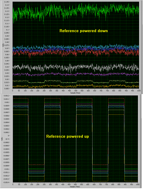
    After another look at your settings, it appears that you may need to change them to get the correct test signal.  For the test signal the Reference Buffer needs to be powered up (Configuration Register 3).

    In the attached, the effects of turning on or off the reference buffer are shown.

    Let us know if there is anything else we can help with.


    Regards,

    Greg

  • Hi Greg!


    I tried the setting for Config Reg 3 you suggested - it worked. The signals now look nice and clean. Many thanks!


    Nevertheless I still have a problem with the software crashing. When I click the acquire button the software displays "DSP collecting data" and just stays in that state. It cannot get the data and doesn´t display it on the analysis tab. I can still change between tabs in the outer bank and also within the analysis tab but the inner bank within the registers tab is grayed out.

    http://yfrog.com/86crashdj

    Also the screenshot caputre and device reset buttons are functional.

    Tom sent me a new board and the same problem with the software is also apparent with that one. But unlike the first board the second one doesn´t even display the device ID or the Rev no correctly.

    http://yfrog.com/3uboard2registersj

    The register map shows that there are only ones written to the registers. This happens whether I reset the board with device defaults or programmed defaults.

    http://yfrog.com/3uboard2registersj

    Changes made to the settings don´t reflect in the register map. The registers just stay filled with ones regardless. I haven´t been able to capture any data with the second board as it has crashed on every try.


    The first board can capture data but only with certain settings. I haven´t been able to recognize a pattern in the settings under which the board crashes and under which it doesn´t. The settings displayed in my previous post seem to be one of the few which are working and with them I was able to verify that the enabling of the reference buffer worked. I´ll also add the register maps of the first board when resetting it with programmed default and device defaults. Maybe they´re helpful to you.

    http://yfrog.com/4wdevicedefaultsj

    http://yfrog.com/2tprogrammeddefaultsj

    If you have any ideas I´m eager to hear them.


    Best Regards

    Kaarel

  • Kaarel -

    The all 1s register map is indicative of a problem where the CS pin is floating and the device isn't initialized/doesn't start up correctly.  In the previous firmware, CS was not set (software control let it float), so we have corrected this in the latest software update.

    Please download the updated software located at the link shown below.

    ftp://ftp.ti.com/pub/data_acquisition/ADS1298EVM/ads1298ecg-fe-0.7.2.exe


    Regards,

    Greg

  • Hi Greg!


    Sorry I wasn´t able to reply any sooner.

    The software update worked. I got my second kit up and running. Thanks!

    The fist one is still buggy. I´ll try to compare their SPI signals to one another. Maybe the first board also has its problem there.


    Best regards

    Kaarel