Because of the holidays, TI E2E™ design support forum responses will be delayed from Dec. 25 through Jan. 2. Thank you for your patience.

This thread has been locked.

If you have a related question, please click the "Ask a related question" button in the top right corner. The newly created question will be automatically linked to this question.

ADS1220: TM4C129ENCPDT - SPI with ADS1220 register read back issue

Part Number: ADS1220
Other Parts Discussed in Thread: TM4C129ENCPDT

Hi,

I am just a beginner to the SPI protocol, I am trying to program TM4C controller using CCS IDE and EK-TM4C129-EXL Board to interface the ADS1220 ADC. I have tested SPI interface in loop back and it is happening, The configurations i have used for spi and communicating to ADC is listed below, register read back is not happening from the ADC, I request you for some help to troubleshoot the issue.

Thank you

////////////////////////////////////////////////////////////////////////////////////////////////////////// SPI configuration

Interrupt_flag = 0xFF; // set flag initially

#if defined(TARGET_IS_TM4C129_RA0) || \
defined(TARGET_IS_TM4C129_RA1) || \
defined(TARGET_IS_TM4C129_RA2)

#endif


ui32SysClock = MAP_SysCtlClockFreqSet((SYSCTL_XTAL_25MHZ |
SYSCTL_OSC_MAIN |
SYSCTL_USE_PLL |
SYSCTL_CFG_VCO_480), 120000000); // Set the clocking to run directly from the crystal at 120MHz.

SysCtlPeripheralEnable(SYSCTL_PERIPH_SSI0);


SysCtlPeripheralEnable(SYSCTL_PERIPH_GPIOA);


GPIOPinConfigure(GPIO_PA2_SSI0CLK);
GPIOPinConfigure(GPIO_PA3_SSI0FSS);
GPIOPinConfigure(GPIO_PA4_SSI0XDAT0);
GPIOPinConfigure(GPIO_PA5_SSI0XDAT1);

GPIOPinTypeGPIOInput(GPIO_PORTA_BASE, GPIO_PIN_6 ); // Interrupt


GPIOPinTypeSSI(GPIO_PORTA_BASE, GPIO_PIN_5 | GPIO_PIN_4 | GPIO_PIN_3 |
GPIO_PIN_2);


#if defined(TARGET_IS_TM4C129_RA0) || \
defined(TARGET_IS_TM4C129_RA1) || \
defined(TARGET_IS_TM4C129_RA2)
SSIConfigSetExpClk(SSI0_BASE, ui32SysClock, SSI_FRF_MOTO_MODE_1,
SSI_MODE_MASTER, 1000000, 8);
#else
SSIConfigSetExpClk(SSI0_BASE, SysCtlClockGet(), SSI_FRF_MOTO_MODE_1,
SSI_MODE_MASTER, 1000000, 8);

#endif

//////////////////////////////////////////////////////////////////////////////////////////////////////////////////////////////////////////////

/////////////////////////////////////////////////////////////////////////// ADC configuration

SSIEnable(SSI0_BASE);

SSIDataPut(SSI0_BASE, ADC_Reset); // Resetting the ADC

Delay_ms(1); // definite delay


pui32DataTx[0] = 0x43; // WREG command to write register
pui32DataTx[1] = 0x01; // Register0 data value
pui32DataTx[2] = 0xD4; // Register1 data value
pui32DataTx[3] = 0x00; // Register2 data value
pui32DataTx[4] = 0x00; // Register3 data value

for(ui32Index = 0; ui32Index < 5; ui32Index++)
{
SSIDataPut(SSI0_BASE, pui32DataTx[ui32Index]);
}

while(SSIBusy(SSI0_BASE))
{
}

Delay_ms(1);
SSIDataPut(SSI0_BASE, 0x23); // Read register

while(SSIBusy(SSI0_BASE))
{
}

for(ui32Index = 0; ui32Index < 4; ui32Index++)
{


SSIDataGet(SSI0_BASE, &pui32DataRx[ui32Index]);


pui32DataRx[ui32Index] &= 0x00FF;

}

////////////////////////////////////////////////////////////////////////////////////////////////////////////////////
 

  • Hi Kurian,

    It is always best to verify proper communications by observing the communication on an oscilloscope or logic analyzer.  One consideration relates to the data length of the SPI peripheral.  If you use the SS portion of the SPI peripheral, the SS will only stay low for the length of communication buffer.  This may be 8 bits, 16 bits or 32 bits.  For the ADS1220 the CS (SS) must stay low throughout the entire communications transaction.  It is often better to control the SS manually by GPIO control.  You can verify by one of the methods stated at the beginning.

    Best regards,

    Bob B

  • Hi Bob,

    Thank you

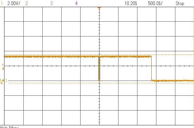
    Sorry for the late reply, I have tried with the scope and as expected the data write to transmit buffer is happening in the following sequence "0x07, 1 ms delay, 0x43, 0x01, 0xD4, 0x00, 0x00  1 ms delay 0x23". The SS pin at master and slave is permanently short to the same ground. while probing MISO of ADC, I am not receiving the expected register configuration sequence but some data is there, please find the same below. Am i right with the register concepts of ADS1220?. Please guide me to troubleshoot this issue. I am using a 100khz SCLK,   

  • Hi Kurian,

    I really don't see anything it your code that would be an issue.  Have you verified that the 1ms delay is actually 1ms?  If there is not enough time between the sending of the RESET command and the WREG command, the second command may be ignored.  You should verify by oscilloscope the time between commands being sent.

    Your scope shots only show one signal.  It would be more helpful to see both the transmitted data and the SCLK to verify that the communication is correct.  In particular the MOSI and SCLK for the register write.  It would appear that you have a 4-channel scope, so I would suggest taking shots with the ADS1220 CS, DOUT, DIN and SCLK.

    Best regards,

    Bob B

  • Hi Bob,

    Thanks a lot,

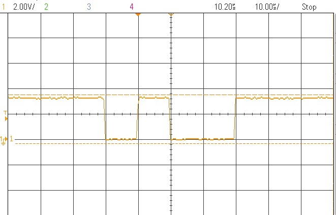
    The issue was with receiving data in absence of clock, so dummy clocks are provided to read the registers. I am sharing my experience for someones useful information; please find the working code and the probed signals.

    ////////////////////////////////////////////////////////////////////////////////////////////////////////////
           SSIDataPutNonBlocking(SSI0_BASE, ADC_Reset);            // Resetting the ADC

           Delay_ms(1);                                                                          // ms delay

           pui32DataTx[0] = 0x43;              // WREG command to write register

           pui32DataTx[1] = 0x01;              // Register0 data value

           pui32DataTx[2] = 0xD4;              // Register1 data value

           pui32DataTx[3] = 0x00;              // Register2 data value

           pui32DataTx[4] = 0x00;              // Register3 data value

           pui32DataTx[5]  = read_ADCregister;

           pui32DataTx[6]  = Start_Convertion;

           pui32DataTx[7]  = 0x00;             //dummy

           pui32DataTx[8]  = 0x00;             //dummy

           pui32DataTx[9]  = 0x00;             //dummy

           pui32DataTx[10] = 0x00;            //dummy

           for(ui32Index = 0; ui32Index < NUM_SSI_DATA; ui32Index++)

               {

                   SSIDataPutNonBlocking(SSI0_BASE, pui32DataTx[ui32Index]);

                   SSIDataGet(SSI0_BASE, &pui32DataRx[ui32Index]);

               }

    /////////////////////////////////////////////////////////////////////////////////////////////////////////////////////

  • Hi Kurian,

    I'm glad you made progress and can now read data from the ADS1220.  Just to be clear, when desiring to read from a slave device the master must issue SCLKs.  For the SPI peripheral to read from the slave, the clocks are initiated by writing to the TX buffer.  This is a NOP (or some value that will not be interpreted as a command which is often either 0x00 or 0xFF) which can be transmitted by the master to initiate the clocks.

    Order of operation is important.  If you don't clear the RX buffer after a write, then you may have garbage data in the RX buffer.  When you read from the slave device, you must make sure that you are reading the desired data and not the previous data.  If you do not clear the RX buffer before writing the NOP to the TX buffer the next RX buffer read may be the old data. So when reading from the device, you should clear the RX buffer then write the TX buffer.  Wait for valid data to be completely written to the RX buffer prior to reading.  This is usually accomplished by polling the buffer flags.

    One other consideration relates to blocks of data transmitted to prevent overruns.  The sequential C code may actually execute faster than you realize.  In most cases the processor is running much faster than the peripheral clocks, so even if you are using a FIFO for your transmit and receive buffers you need to be very careful that you are not missing data either transmitted or received.  Again, this can be accomplished monitoring the transmit and receive flags.

    Best regards,

    Bob B

  • Hi Bob,

    I appreciate your quick response, thanks a lot dear Bob. for me it was a learning step towards SPI, ADC ADS 1220 and TM4C129ENCPDT