This thread has been locked.

If you have a related question, please click the "Ask a related question" button in the top right corner. The newly created question will be automatically linked to this question.

DAC7728: Power-up problem

Part Number: DAC7728


Hello,

I have design a pcb board, which 2 DAC7728, my configuration:unipolar output, i don't use the  correction engine, 15V for AVDD, IOVDD is connected to DVDD and is 5V, i dont use LDAC
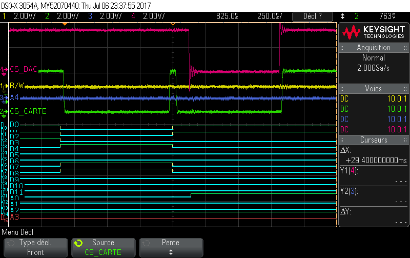
Some time one is not starting (all time the same), and any command i will send is not executed. (ex: test GPIO)
I restart the board, and this is ok.

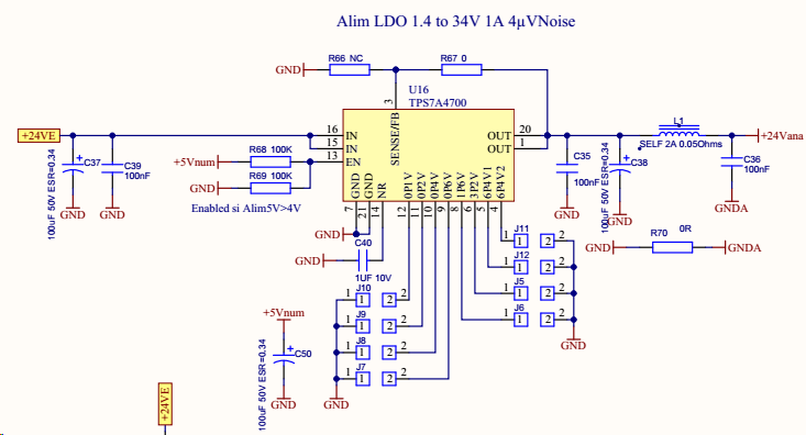
I give my schematic:
The power supply +24Vana is configured to 15V.
The DVDD is set firt, and AVDD and REFA/B.
I have had pull up (47K) in CS pin of DAC, no change.

Do you have timing specification for the setting time of power-supply?
Or is it other problem?

  • Hello,

    When I put voltage on a DVDD/IOVDD, it's possible that a voltage stay on pins of condensators (Vref and AVDD).
    Is it possible that my problem come from this remainder of voltage ?

    Thanks
  • Hi Greg,

    Thanks for your query. In order to understand the power sequencing, the best way would be to probe all the power pins during power on/off.

    Could you please do that for both success and failure cases and attach the waveforms?

    Regards,
    Uttam Sahu
    Applications Engineer, Precision DACs
  • Blue color: DVDD/IOVDD

    Green:  AVDD

    pink: REFA/REFB of first DAC

    yellow:: REFA/REFB of second dac 

    Note: pink and yellow trace is same

    DAC1 not working, DAC2:working

    Start-up:

    Power-down

    Power-down zoom

    Thanks

  • I have 2 board: on which the 2 DAC and on other with a microcontroller (LPC1778).

    I see,3 day of which follow each other, the morning i don't have any problem, and the afternoon the first DAC don't working.

    The difference, is the temperature, more hot the afternoon.

    I have refresh my DAC board, no change, i refresh my micro board, the first dac is work.
    I change in loop the value of the dac for testing, and i heat my micro board, the DAC stop to change.
    I attach the scop of data communication,
    For send data to dac, i use 2 times (8bits bus).
    First time set address and high data bit, and latch it,
    Second time send 8 last bit data and unlock addresses and data
    In the second time 12 bits data and 5 bits address is send to DAC

    On the scop, the interest time for the DAC is when the pink trace is low (CS_dac), the value send is 2051 adress is 8 .

    My RD/WR is all the time low except when we read.

    The good:

    The bad:

    Thanks

  • Hello,

    In page 12 of datasheet of DAC7728, this is not very clear:
    The read operation is in falling edge of CS and data is valid on rising edge of CS.

    And write operation 1, write is validated at falling edge of CS, but why we have the t2 and t4 time?

    Thanks

  • Hi Greg,

    The timings t2 and t4 are the setup times for CS from R/W and Address, respectively. These lines should have settled before the CS is activated.

    Regarding your main question, the power sequencing looks correct although you have not given the sequence when the board fails.

    On the temperature related failure note, I would say this is strange unless the temperature is high enough to make/break some connectivity on the PCB. There should not be any issue with the device itself. I would suggest you to have the board touched-up with solder and cleaned properly before testing again. Most of the time a dry solder or minute contaminants are cause of these kind of behavior.

    Regards,
    Uttam
  • HI,
    Thanks for your reply.
    The power sequence is same when board is fail.
    In my previous picture of oscillo, the D8..D11 is after CS , but respect the timing t6.
    The D8..D11 is buffered, i have change the enable output of buffer to set D8,D11 in same time than D0..D7, the result is more good.
    Other question: is it possible to read the 8 DAC data register?
    When i read it, it send 0 in my oscillo .
    Thanks
  • Hi,
    I have the solution:
    I have build second pcb board, and it work well, but it is not possible to read the DAC data register.
    I have test to send data to VMON register, and i read it, this is the same value.
    My solution for be sure that the DAC is respond: i send data to data register and same data to VMON register and read Vmon register.
    Note I dont use VMON pin.
    My conclusion for the firts pcb board, output pins and data input pin of the DAC is not protected to short-circuit, or CEM problem.

    Problem resolved.
  • Hi Greg,

    Good to know that the problem got resolved.

    Regards,
    Uttam