This thread has been locked.

If you have a related question, please click the "Ask a related question" button in the top right corner. The newly created question will be automatically linked to this question.

ADS7952: ADS7952 / Write/Read sequence in Manual Mode

Part Number: ADS7952

Hi,

Please advise me about SPI of ADS7952.


Here is the expectation of Write/Read sequence after Power-up. Is it correct?


-> Power-up (adhere to "Power Supply Recommendations")

                     (Interval : >10mS)

                            -> 1st Frame         Write [Mode: Manual, MUX: Ch1]

                                                        Read [invalid]

                             -> 2nd Frame        Write [Mode: Manual, MUX: Ch2]

                                                        Read [12bit conversion result of Ch1]

                             -> 3rd Frame         Write [Mode: Manual, MUX: Ch3]

                                                        Read [12bit conversion result of Ch2]


On the customer's system, we found the sequence seems necessary to put 1st Frame as "Dummy" for reading out a valid data as below. Could you let me know your considerations?


              -> Power-up (adhere to "Power Supply Recommendations")

                     (Interval : >10mS)

                            -> 1st Frame         Write [Mode: Manual, MUX: ---] ---> Dummy

                                                        Read [invalid]

                             -> 2nd Frame        Write [Mode: Manual, MUX: Ch1]

                                                        Read [invalid]

                             -> 3rd Frame         Write [Mode: Manual, MUX: Ch2]

                                                        Read [12bit conversion result of Ch1]

Best Regards,

Satoshi / Japan Disty

  • Hello Satoshi-san,

    The first sequence should be the correct one according to Figure 49 of the datasheet.
    What are the actual values they are setting the control register to?

    -> Power-up (adhere to "Power Supply Recommendations")
    (Interval : >10mS)

    -> 1st Frame Write [Mode: Manual, MUX: Ch1] (what hex value are they sending to the register?)
    Read [invalid]

    -> 2nd Frame Write [Mode: Manual, MUX: Ch2] (what hex value are they sending to the register?)
    Read [12bit conversion result of Ch1]

    -> 3rd Frame Write [Mode: Manual, MUX: Ch3] (what hex value are they sending to the register?)
    Read [12bit conversion result of Ch2]

    Mike
  • Hi Mike,

    Sorry for my delayed response. Please let me ask again if my understanding is correct.

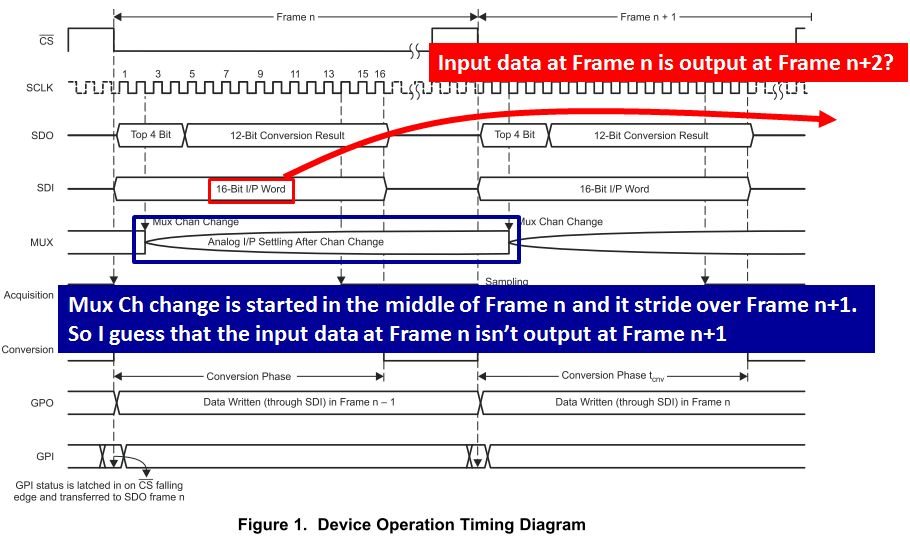
    From Fig.1 in datasheet, the input data at Frame n may be output at Frame n+2, because Mux Ch change is started in the middle of Frame n and it stride over Frame n+1. Can you please give your opinion about this?

    Best Regards,

    Satoshi / Japan Disty

  • For your additional information, my customer is evaluating ADS7952 actually and confirm following result.

    • When the Mux ch is not changed, the input data at Frame n is taken at Frame n+1
    • When the Mux ch is changed, the input data at Frame n is taken at Frame n+2

    Thanks

  • Hello Satoshi-san,

    When you write to change the mux at n the data should come out at n+1.  Please see figure 50.  This shows that for example in frame n the device will be sending out the conversion data for frame n-1.  Also in frame n you re programming for frame n+1.

    Mike

  • Hello Satoshi-san,

    The datasheet is unclear on this. It does look like the data comes out on n+2. Please see this post:

    e2e.ti.com/.../1077037

    Mike