This thread has been locked.

If you have a related question, please click the "Ask a related question" button in the top right corner. The newly created question will be automatically linked to this question.

ADS124S08EVM: Delta-Sigma ADC Evaluation Software for ADS124S08EVM

Part Number: ADS124S08EVM
Other Parts Discussed in Thread: ADS131A04, ADS124S08

Hi,

ADS124S08EVM's Evaluation SW is installed to our PC/ Windows7 and downloaded required .net files.

But register map settings are inactive and two times installed the SW and the same issue.

With another PC tried and same resposne.

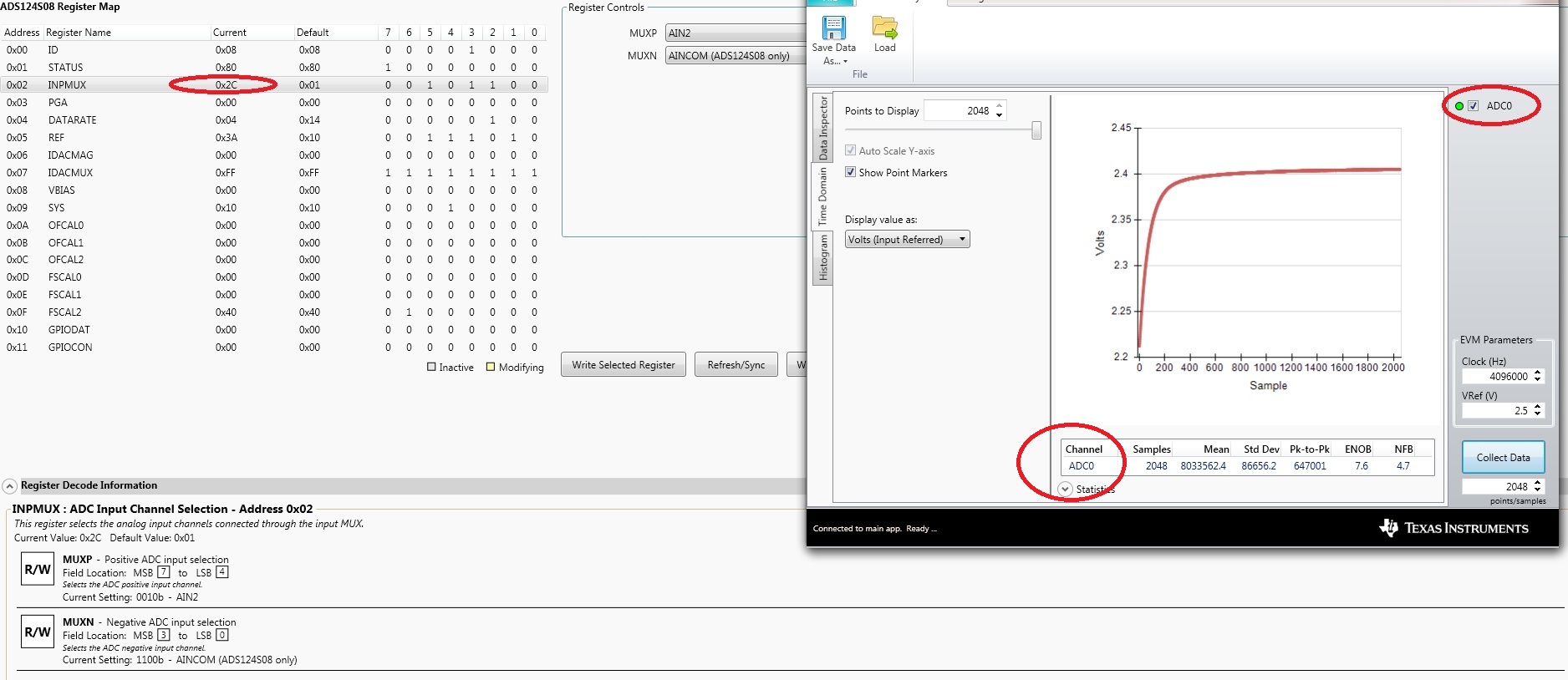
Provide the solution to debug the EVM with proper SW tool.  And snapshot is attached for reference.

  • Hi Mallikharjuna,

    There are actually two parts to the software installation.  You have installed the main GUI application, but each EVM has its own device package installer with all the information regarding the device to be evaluated.  So one main GUI for many possible devices and one device package for each different EVM you wish to connect.

    From the tools folder:

    http://www.ti.com/tool/ads124s08evm

    Download and install the device package for the EVM.  All information is given in the user's guide which can also be downloaded from a link in the same tools folder on the web.

    Best regards,

    Bob B

  • Hi Bob,

    Thanks for support, now able to change all the registers.

    But there is a issue of ADC channel selection in Analysis Engine.  If configure any channel then anlysis engine is showing only ADC0.

    Another issue is without any analog input, the output is sitting in reference voltage whether it is internal or external.

    We tried with external controller to configure the ADC, eventhough same senario is coming.

    Please provide the solution and we are stuck to selection of ADC for our product.

  • Hi Mallikharjuna,

    I've had a very similar question on the forum:

    https://e2e.ti.com/support/data_converters/precision_data_converters/f/73/p/607935/2246925#2246925

    A floating input can float to any value from AVSS to AVDD.  You should not expect the input to be zero, or some consistent value.  If you want to measure a voltage you must supply a voltage, or force the input to a known state.

    The ADC0 indicator is a bit confusing.  All this means is an ADC data channel has been collected.  The GUI supports many devices. The ADS124S08 only has one output data channel so it will always indicate as ADC0.  However, devices such as the ADS131A04 has multiple simultaneous converters so you would see ADC0, ADC1, ADC2 and ADC3.  The check boxes allow the channel data to be turned on/off.  So ADC0 has nothing to do with the input channels selected through the mux.

    Best regards,

    Bob B


  • Hi Bob,

    Thanks for info, further any issues will let you know.