This thread has been locked.

If you have a related question, please click the "Ask a related question" button in the top right corner. The newly created question will be automatically linked to this question.

TLV5535-Q1: Looking For RF Signal To Digital Bit ADC Solution

Part Number: TLV5535-Q1

We're Looking For RF Signal Sampling Direct ADC Solutions For Translating Signal Sine Wave From AM / FM Radio Tuner Signal Into Digital Bits. We Find Following Product Page And By Filter Reach Your Products Below:

TLV5535-Q1 / ADC08B200-Q1 / ADS5204-Q1 / ADC10040-Q1

( We're Not Sure Which One In Our Case For Carrier / Detect Is Suitable One )

Our Design Requirement Is To Gain Signals From Antenna / LNA  Which Can Be Categorized As Front-End In Circuit And Divide The Signals Into Carrier / Detect Wave Then Convert Them Into Digital Bits. We Want To Use The Bit To Visualize Radio's Sine Waveform (A Vibration Peaks And Time XY Quadrant Organized In Array Form And Bit Format ). From The Following Captured Example Picture It Seems You Have Purposing Solutions To Meet Our Requirements. Can You Recommend A Design Reference If You Have One Similar To What I Want / Suggest Part Set RF To Bit ADC ( And We May Need Another RF Signal Processing Use Microcontroller Along With The ADC ).

  • Bright,
    We are looking into this.
    Regards,
    Jim
  • Hi,

    I would take a look at the documentation for the ADC32RF80 to start with, and then as you firm up your plans around what sample rate to best use and what features you need consider related devices in that family of devices.   In fact that figure that you copied into your posting from our RF sampling page is a simplified block diagram of the ADC32RF80 even through the part number of the device in that figure was not mentioned. 

    The ADS32RF80 is a 2-channel ADC that can sample at rates of up to 3Gsps, which may be more than you need, but its minimum sample rate of 1500Msps might be plenty adequate for the bandwidth of the signals you wish to sample.  The 'RF80 has four Digital Down Convert (DDC) blocks in it with Numerically Controlled Oscillators (NCOs) to let you digitally choose a portion of the frequency spectrum to zoom into and output.   A traditional radio architecture might involve a local oscillator and a mixer to demodulate the desired signal down from the carrier frequency to a lower intermediate frequency or even down to baseband so that an ADC can sample it.  The idea behind the RF sampling devices such as the 'RF80 is to sample the modulated signal directly after the antenna and amplifier, and then digitally do the demodulation.   The 'RF80 will allow the NCO to be programmed to select the portion of the RF spectrum that you wish to look at, and with as many as four DDC blocks in the device you would even be able to tune into as many as four different portions of the spectrum at a time.  In fact, that portion of the picture on our RF sampling web page that points to Band1 and Band2 in the spectrum is an example of using two of the DDC blocks with the NCO for each DDC set to look at that specific band.

    Is that essentially what you wish to accomplish?  If so, you would still need to design an amplifier section to take the signal from the antennae and condition it for input to the ADC, but from there the ADC DDC blocks may be used to tune in to any portion of bandwidth in the spectrum.

    If this looks to be what you wish to accomplish, then the ADC32RF80 is available on an EVM that connects to the TSW14J56 FPGA capture card.  The HSDCPro GUI that connects to the FPGA capture card will let you analyze the digital data captured from the ADC output.   You would still need to get a reference design for the LNA and signal conditioning in front of the ADC.

    Regards,

    Richard P.


  • Richards

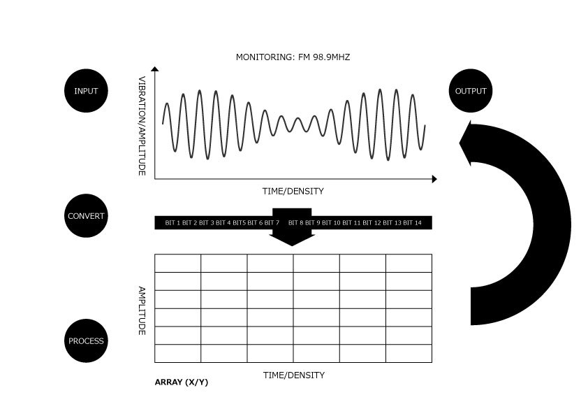
    First Thank You For Your Recommendation And Descriptions For What ADC32RF80 Can Do. But I'm Still Not Sure ADC32RF80 Is What I'm Looking For. Just Clarify The Design Purpose Again Here Wish You Can Leave Some Opinions For Our Use Case. What We're Seeking Is A Simple RF Signal ADC To Bit Solution. My Purpose Is To Have Source To Judge AM/FM Listening Quality By Signal Measurement. So I Need Some Devices Can Be Placed In RF Front-End (Between Antenna / LNA). In Fact We're Gonna Design An AM/FM Radio Tuner With Silicon Tuner Solution And Plan To Find A Easy-To-Use RF Signal Converter By Which We Can Directly Transform RF Signals Into Bit Set And Through An DSP / MCU To Process The Incoming Bits For Making RF Patterns. The Patterns Shall Be Bitstreams And Each Bitstream Shall Be A Frame With Enough Information To Depict The Variations Of Specific Band's Signals Like Below:

    My Question Are Here:

    1. Does Your RF Signal ADC Can Directly Convert Signals Into Bits?

    2. What Will The Converted Data Look Like When Using ADC32RF80?

    3. Attached Picture Shows You What I'm Gonna To Do. I Want To Use A RF-Purposing ADC To Transform Signals Into Bitstream. Each Bitstream Shall Contains Information For Amplitude And Time Of A Listening AM/FM Band. Is Your ADC32RF80 Capable Of Doing That? (The Signal Picture Means A Signal Continuation Sample Don't Confuse With AM/FM Modulation Concept). 

    4. If I Want To Process The Converted Data Which DSP / MCU Do You Recommend Along With ADC32RF80?

  • Hi,

    All of our high speed analog to digital converters convert an analog input signal to digital bits.  That is what A to D converters do.  But our ADC will have requirements on the incoming analog signal, such as the requirement that it be differential, biased to a certain voltage level, and of a certain max amplitude.   There will generally be a signal conditioning block before the ADC, and you mention something about "between antenna/LNA".  If you want something that has the amplification and signal conditioning integrated in with the ADC then no, the ADC32RF80 is not that.    All of our ADC devices will output digital samples and what you do with the digital samples is up to you - for example, if a 14bit ADC is clocked at 500MHz, then you would get 14bit digital samples at 500MSps.  What you do with the digital data is up to you.  We do not have DSP blocks of logic integrated in with the ADC.  The typical application is 1) signal conditioning, 2) ADC, 3) FPGA for processing the data.  In some applications the FPGA may hand the data off to a DSP chip, or in a few applications the DSP chip may take the data directly from the ADC.  But you would have to design your own processing.  For example, there is a TI Design with the 'RF80 into a TI DSP, but the DSP forum would support that TI Design, not here.  http://www.ti.com/tool/TIDEP0081?keyMatch=null&tisearch=tidesigns    But this is just an example.   Design of the signal conditioning before the ADC would more appropriately be in the amplifiers forum.

    Regards,

    Richard P.

  • Hello Richard

    Again Thank You For Your Kindly Reply To My Questions.

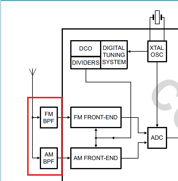
    But I Think You Misunderstood What I Said. I Don't Want A Total Solution Integrated Amplification / Signal Conditioning With ADC. In Stead I Just Want Single Device To Convert Signals Into Bits As You Said What ADC Does Is. I Just Want To Check What Will The Converted Bitstream Look Like? Take Your Case For Example Is The Output A 14 Bits Parallel Bitstream Using 14 GPIOs?  And In Fact I Don't Have A Pictorial Idea Where Should I Put The Device? If I Want To Sample FM / AM Signals  Should I Place The ADC32RF80 After Antenna? And As I Talked About We Would Use Silicon Tuner To Design AM / FM Radio Tuner Circuits Which Means Here's Only One Choice To Place ADC32RF80 Like Below Red Marked Square:

    And The ADC32RF80 Seems Too Powerful To Our Use Case. We Just Want To Monitor The AM / FM Signals (Or Measure Carrier / Detect Then Compare Them To Judge Listening Quality Of Receiving Signal Transmitted By Current Selected Radio Station). Any Recommended Replacements Of ADC32RF80?

  • Although Your Recommended ADC32RF80 Series Seems No Automotive Grade Parts To Select. We Need Automotive Rating And Not Sure Which One Would Be Suitable:
    TLV5535-Q1 / ADC08B200-Q1 / ADS5204-Q1 / ADC10040-Q1
  • It would appear that you have already used the TI device selection page to filter for the automotive devices, as the four devices you mention are the ones listed for automotive.

    Of those, the ADC08B200 is the highest sample rate listed at 200Msps, which would not quite be enough for the Nyquist limit to include the frequency band you are looking at.   None of the devices listed have the features to do direct RF sampling and downconvert to focus on a portion of the spectrum, but ADC08B200 comes closest to covering the spectrum.   If you must choose one of these four devices, then you may need to use a local oscillator and demodulator to down convert before sampling.

    Regards,

    Richard P.