


Hello TI,
I got test result and some questions for ADS42LB69.
l Question
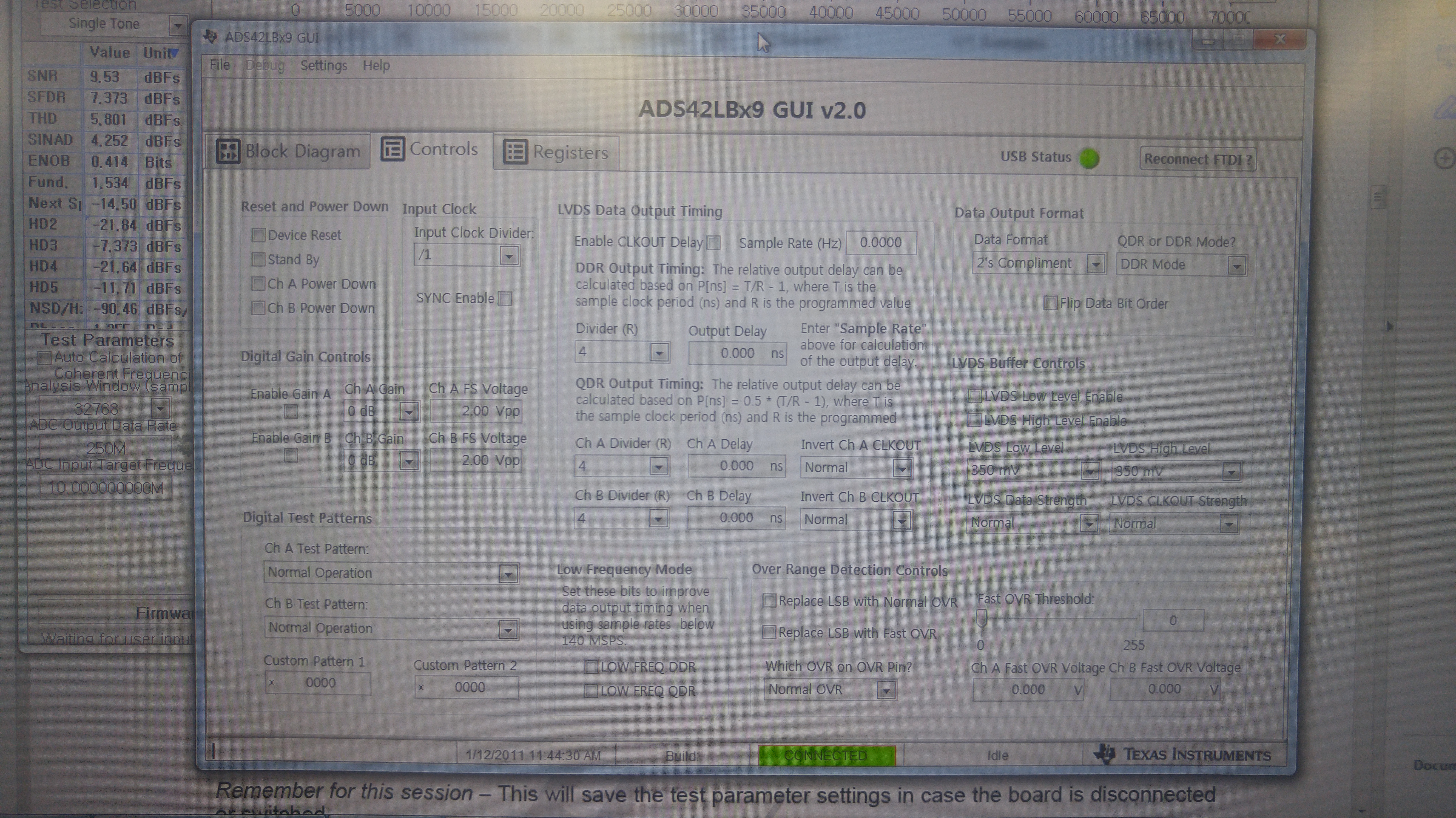
- Please kindly refer to my test result with settings for ’ADS42LBx9 GUI’ and ‘High Speed Data Converter Pro’ and let me know how to get the same result on ADS42LBx9EVM User's Guide. In my test, Clock Input was 250MHz and Signal input was 10MHz.
- If I should use bandpass filter for Clock and Frequency input, should I also use bandpass filter on my custom board? Please provide reference schematic for clock and frequency input.
- My target clock input is 246MHz with 61.5MHz input frequency. Please let me have proper setting values for ’ADS42LBx9 GUI’ and ‘High Speed Data Converter Pro’.
- I found that LVDS output clock frequency and level was changed by choosing Divider. Can I use Divide-by-1 for clock input is 246MHz with 61.5MHz input frequency?
l ISSUE (ADS42LBx9EVM Test)
- Unexpected components on captured data using TSW1400 as below.

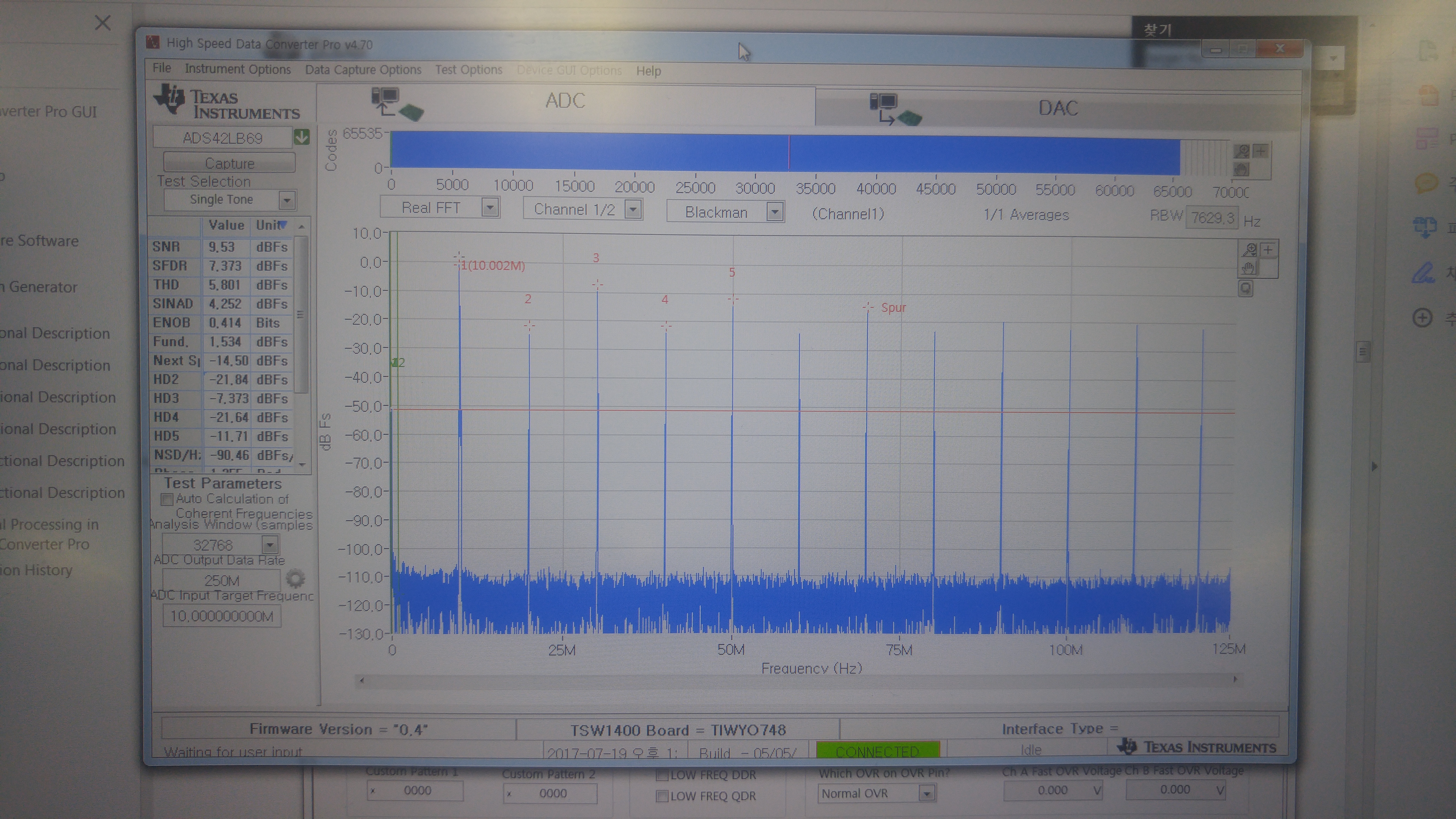
l Test Result
- Followed ADS42LBx9EVM User's Guide in http://www.ti.com/lit/ug/slau465a/slau465a.pdf
- Bandpass Filter
Since I don’t have bandpass filter, I couldn’t follow below instructions. So I tried to use Low Pass Filter for 10MHz frequency input, but test result was same.
- Connect a signal source to either analog input SMA connector, A_INP or B_INM. For single-tone testing, a bandpass filter should be used to achieve the best SNR and harmonic performance.
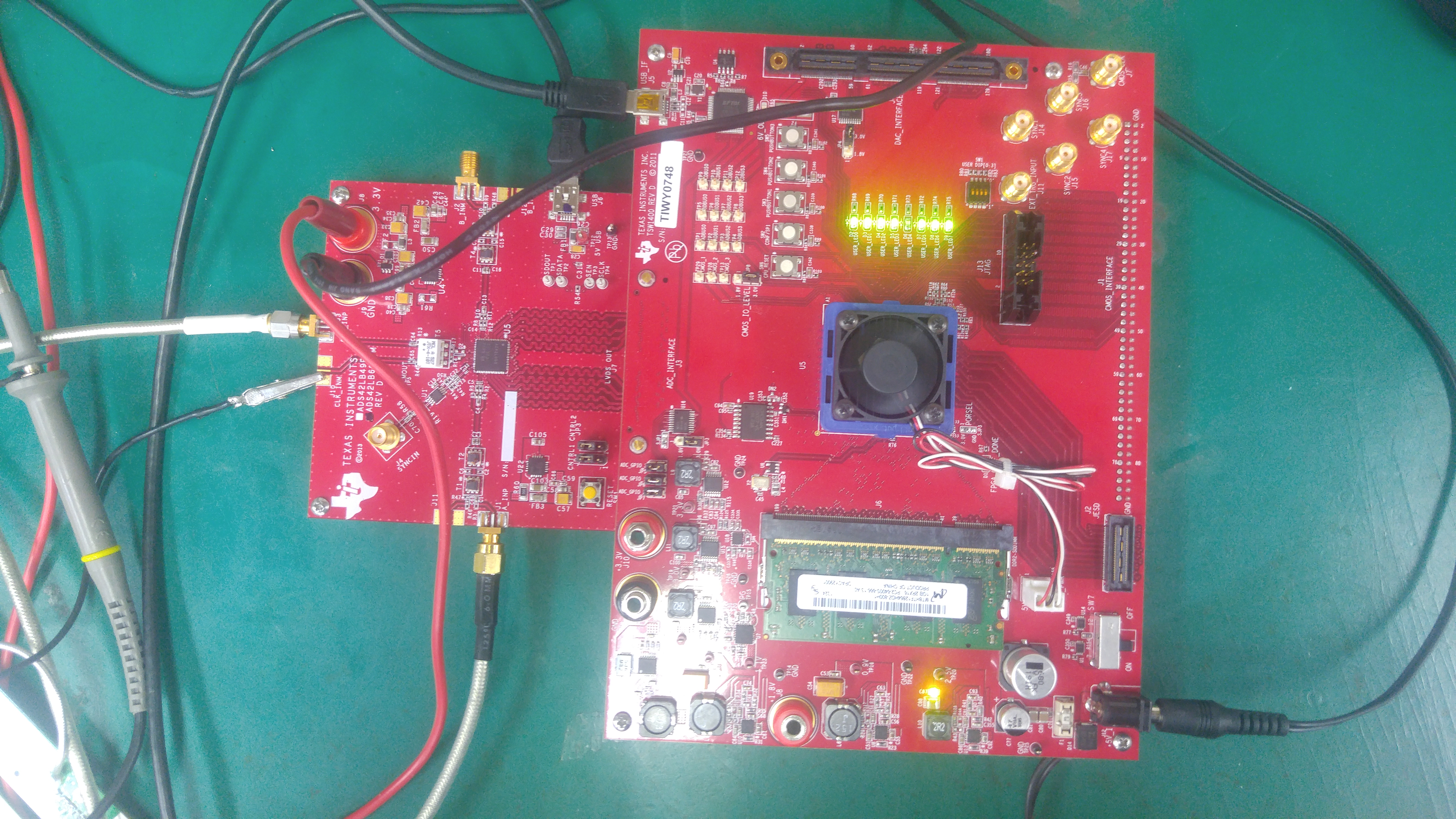
- Connect the ADS42LBx9EVM to the TSW1400 by connecting J7 on the ADS42LBx9EVM to the ADC Interface connector on the bottom of the TSW1400.
3. Settings for ’ADS42LBx9 GUI’ and ‘High Speed Data Converter Pro’
Please refer to the settings that I used for this test as below.
Best regards,
Shaka
