Hello, everyone.
I have made the system using three ADS1299EEG EVALUATION board and one STM32F4 Discovery board. I configure the three ADS1299s in the Daisy-Chain mode. The three ADS1299 share the same /CS, DIN, SCLK, CLK and power signals. The second and third ADS1299s' /DRDY are floating and not connecting to any pins. The first ADS1299's /DRDY signal is connected to STM32 as an external interrupt input. The DOUT PIN of the second ADS1299 is connected to the first DAISY-IN and the DOUT of the third ADS1299 connected to the second DAISY-IN of the second ADS1299. The DAISY-IN pin of the third ADS1299 is connected to GND.
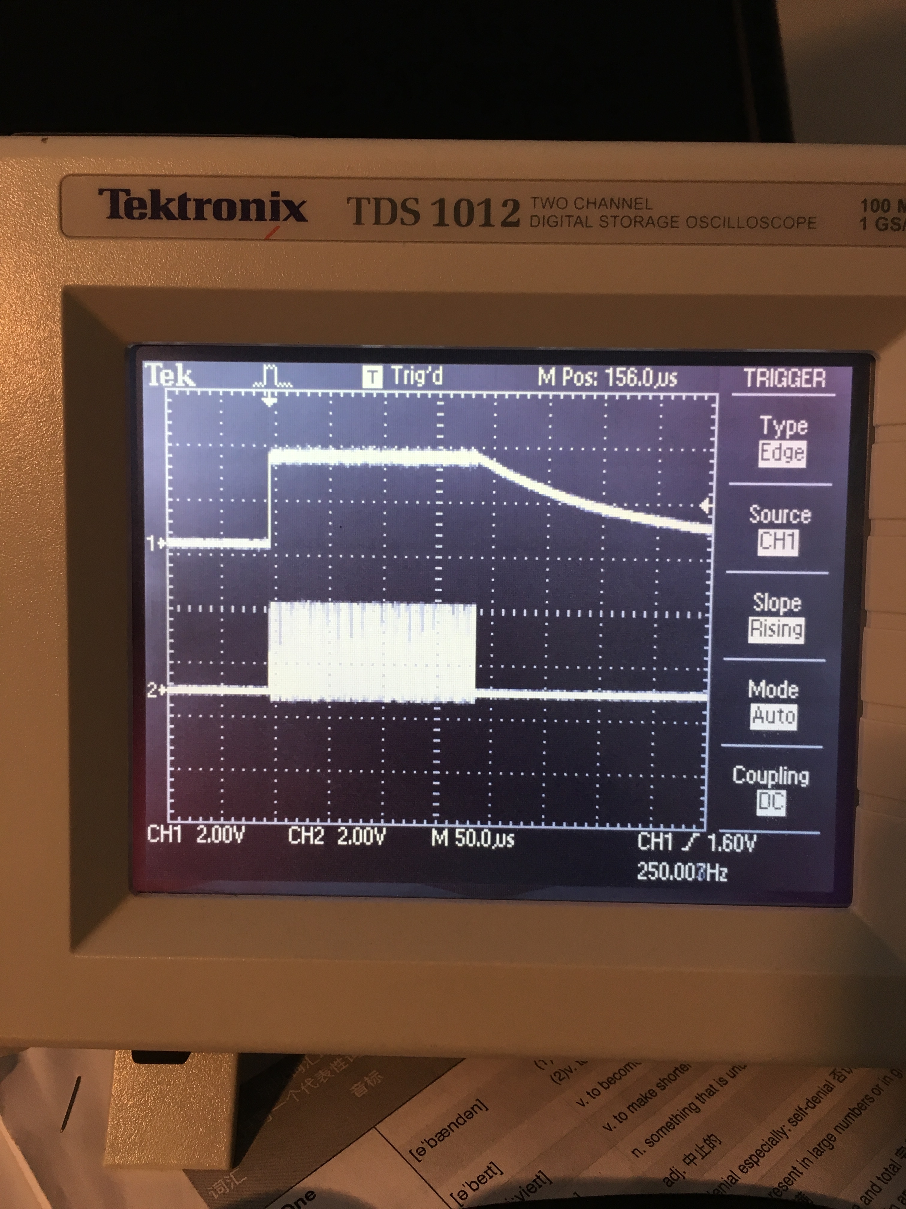
Now I can write and read the register of the first ADS1299 and when the data conversion begins the /DRDY pin triggered correctly. But the data I read from the ADS1299s is 0xFF and there is a long 'tail' after the data. It shows below.
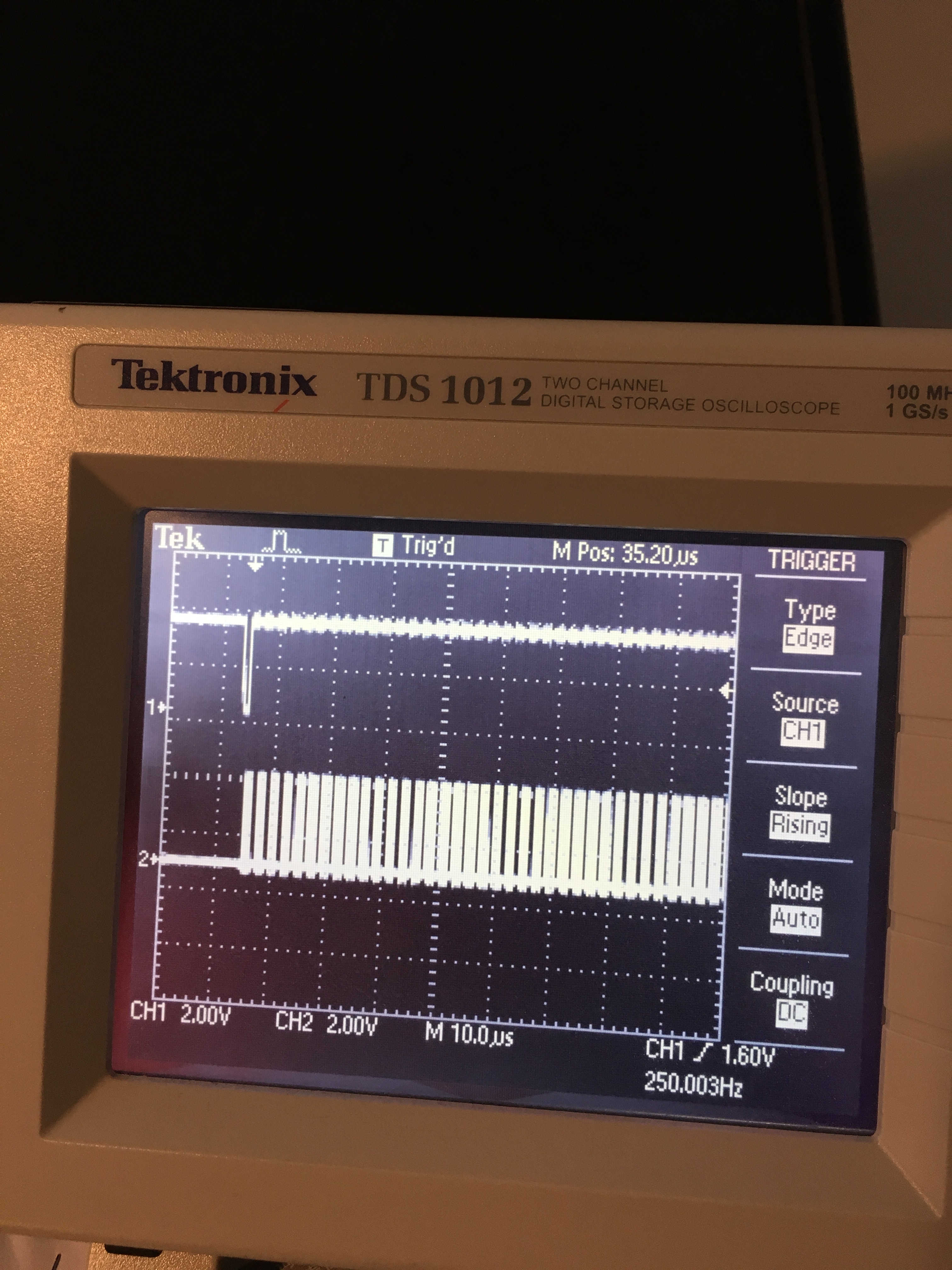
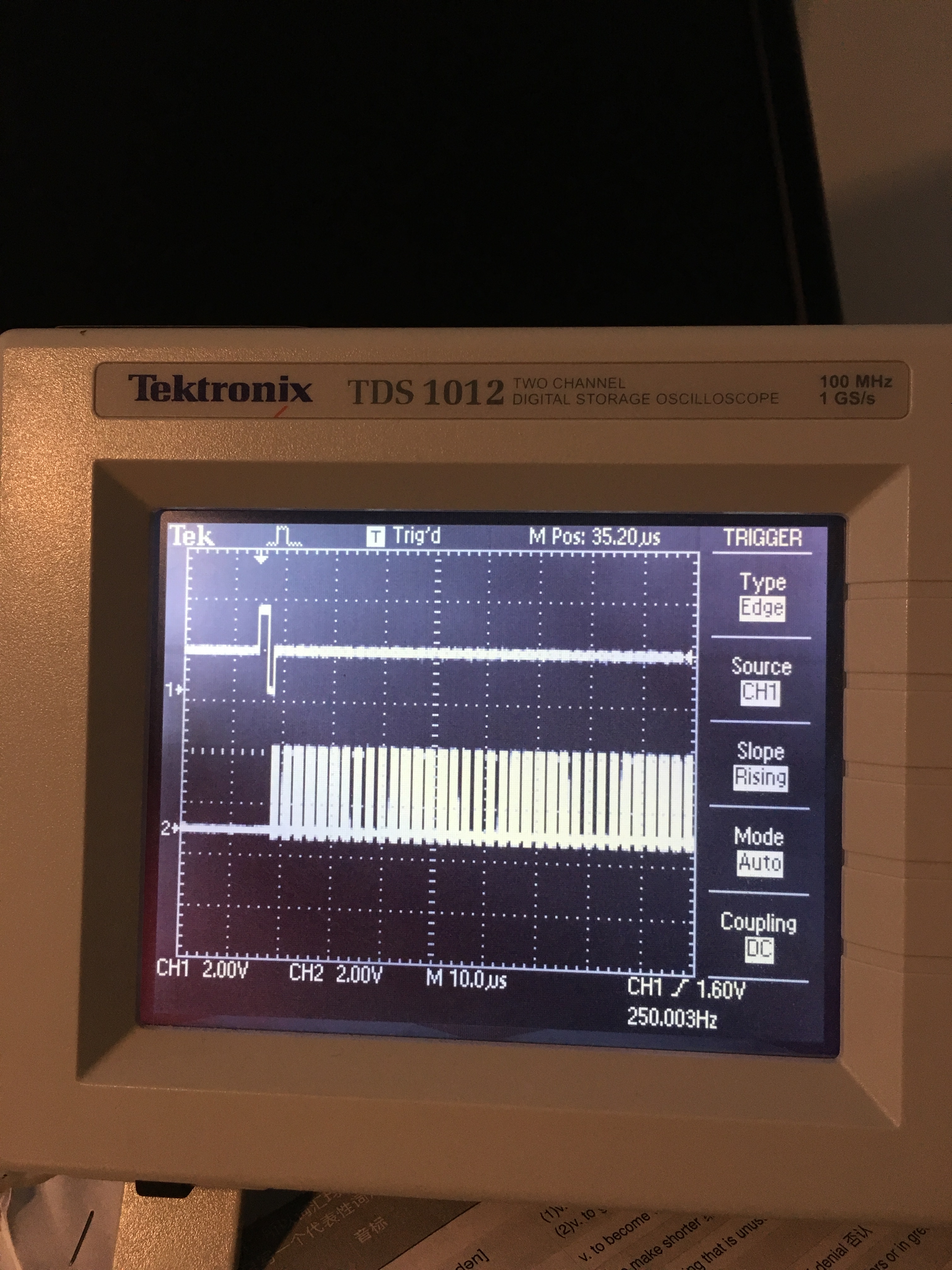
The first picture is SCLK and DOUT of first ADS1299, which the upper is DOUT and the lower is SCLK. The second to the fourth picture is /DRDY pin of the three ADS1299s. I think the /DRDY pins of three ADS1299s are synchronized. But the data is wrong. Anyone met this thing ever before. Please help me, thank you very much.