Part Number: DAC8775EVM
Other Parts Discussed in Thread: DAC8775
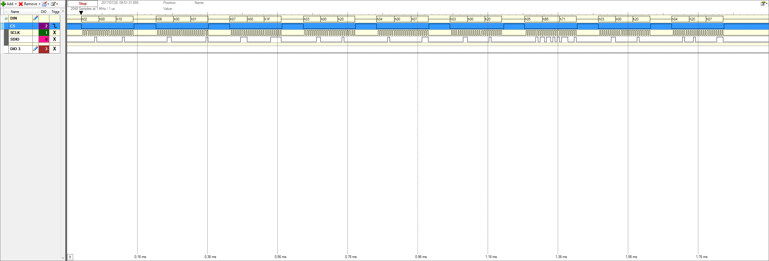
I can't get an Output current when sending commands via a microctonroller (STM32H405 board by Olimex and a clock of around160kHz and a Level of 3,3V) to the DAC8775. The sequence of commands first selects the internal reference, then turns on the Buck/Boost for channel A, then writes the desired DAC value in Register 05 and then turns on the Output. The commands sent are as follows:
h02h00h01 //to turn on the internal reference
h06h00h01 h07h00h1F //to select Buck/Boost for channel A and to turn on both arms of the Buck/Boost converter
h03h00h20 h04h00h07 //to select current Output and to set it to -24mA Output current
h03h00h20 h05hB5h71 //to set the Output to 10mA (the DAC value was measured)
h03h00h20 h04h10h07 //set the Output to -24mA and turn on the Output
When sending the commands I get a reply via the SPI that I am measuring aswell.
I have made sure to connect all Pins to their respective Levels. LDAC and clr are set to low. RESET is set high (5V) after powering up the device. I power up the device using a DC/DC converter that provides 15V (the voltage Level was checked and works with the SM-USB-DIG). I made sure that the SCLK and CS signals do not crosstalk (measured using a LeCroy - WaveSurfer 44MXs-B).
I hope you can help me find the mistake I am making.
Best regards Arne