This thread has been locked.

If you have a related question, please click the "Ask a related question" button in the top right corner. The newly created question will be automatically linked to this question.

PGA411-Q1: Angular values read unstable

Part Number: PGA411-Q1

Hi~ 

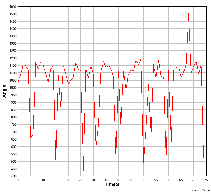
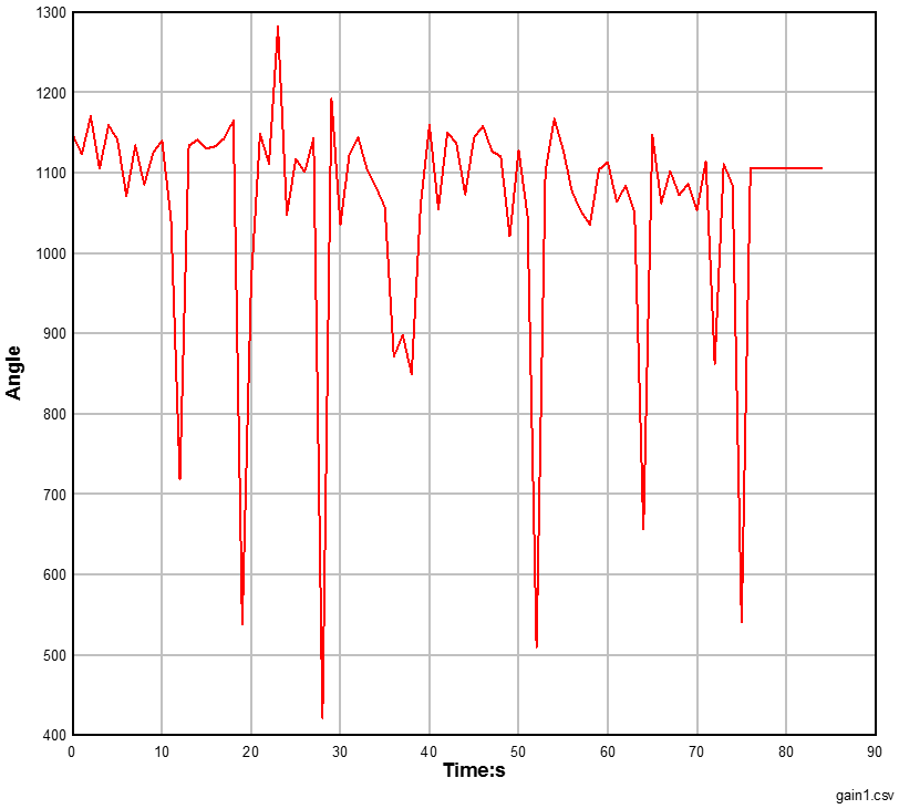
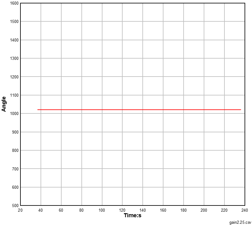
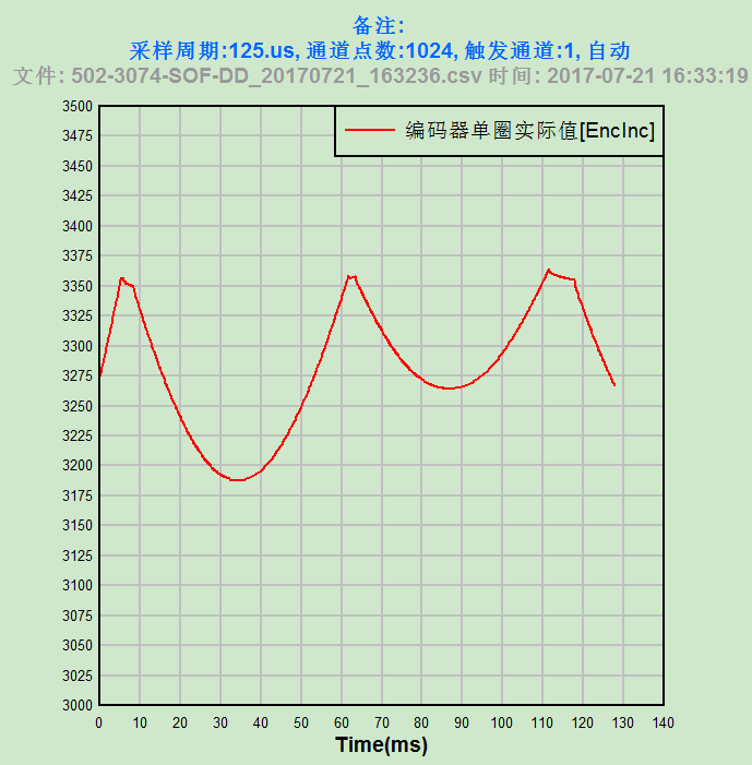
(1)When the motor is in a fixed position (which is always in sinθ = 0 or cosθ = 0), the angle values which are stored in DEV_STAT5 register are always changing from 2 to 170 incs.Please see the graph below, What's the reason for that?

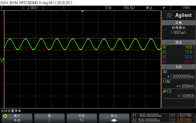
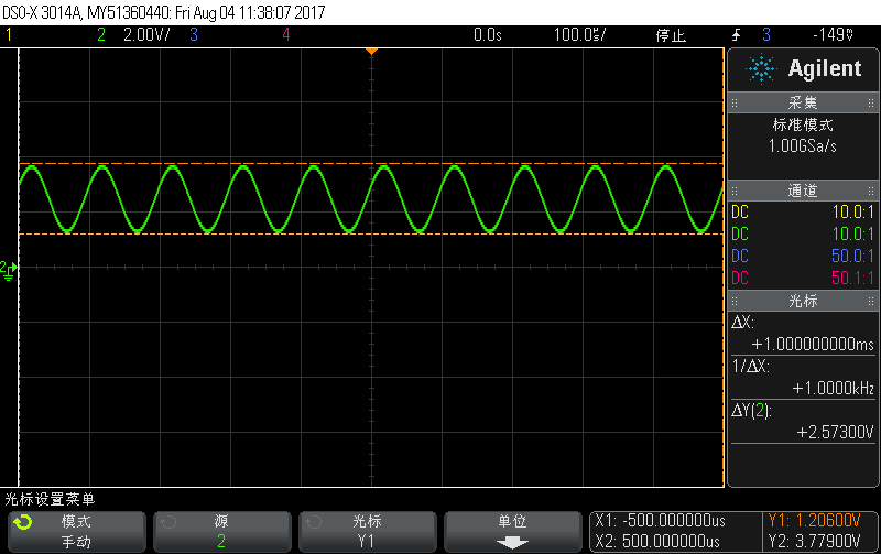
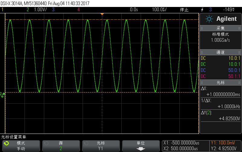
(2) For best accuracy performance, TI recommends that the IZx differential voltage (Vpp) is between 600 mVpp and 1.5 Vpp as measured at the OSIN and OCOS pins. What is the recommended voltage and the single ended vlotage on the OSIN and OCOS pins?

Best regards,

Thanks.

  • 1.) Can you send me your register settings?
    2.) the voltage on the OSIN and OCOS pins should be centered around 2.5V, and should stay within 0.5V to 4.5V single-ended. Having a larger signal will help with noise immunity as well, so feel free to increase the OSIN/OCOS signal to be around 2Vpp.
  • Hi Clancy,
    1) The input voltage/frequency of the resolver we used is AC 7Vrms/10kHz.
    The registers are setting as below:
    [DEV_OVUV1] = { 0x8B40},
    [DEV_OVUV2] = {0x00ED},
    [DEV_OVUV3] = {0xFCFF},
    [DEV_OVUV4] = { 0x07F0},
    [DEV_OVUV5] = {0x1C00},
    [DEV_OVUV6] = {0x038F},
    [DEV_TLOOP_CFG] = {0x0514},
    [DEV_AFE_CFG] = { 0x0005},
    [DEV_PHASE_CFG] = {0x1800},
    [DEV_CONFIG1] = {0x0005},
    [DEV_CONTROL1] = {0x0000},
    [DEV_CONTROL2] = {0x0000},
    [DEV_CONTROL3] = {0x0003},
    [DEV_STAT1] = {0x0000},
    [DEV_STAT2] = {0x0000},
    [DEV_STAT3] = {0x0000},
    [DEV_STAT4] = {0x0000},
    [DEV_STAT5] = {0x0000},
    [DEV_STAT6] = {0x0000},
    [DEV_STAT7] = {0x0000},
    [DEV_CLCRC] = {0x003F},
    [DEV_CRC] = {0x0000},
    [CRCCALC] = {0x00FF},
    [DEV_EE_CTRL1] = {0x0000},
    [DEV_CRC_CTRL1] = {0x0000},
    [DEV_EE_CTRL4] = {0x0000},
    [DEV_UNLK_CTRL1] = {0x0000},
    The DEV_OVUV4, DEV_CONFIG1,DEV_PHASE_CFG registers are modified, others are the default values.
    2) When the angle values which are stored in DEV_STAT5 register are always changing, the single ended voltage on OSIN or OCOS pin is between 1.45V to 3.5625V or 1.7V to 3.3V. Does this matter?
    Thanks.
  • Hi ~Clancy,

    Having a larger signal will help with noise immunity as well, so feel free to increase the OSIN/OCOS signal to be around 2Vpp.

    How to calculate the 2Vpp?

    For example, if the OSIN/OCOS single-ended voltage is from 0.5v to 4.5V,  the OSIN/OCOS signal is around 2Vpp((4.5 - 2.5)Vpp or  (2.5 - 0.5)Vpp), is this right?

  • OSIN/OCOS should be centered around 2.5V. When you measure OSIN or OCOS single-ended, 2Vpp will go from 1.5V to 3.5V.
  • Hello Calncy,

    Thanks for your reply,

    When the motor output angle is near 1023(θ=90°, cosθ = 0),

    (1) Set the GAINCOS=GAINSIN=0.75,  angle values read unstable. The waveform of osin is shown in Figure 1. Figure 2 shows the angle  position output values .

                                                                                                      Figure1. OSIN signal                                                                     

                                                                                Figure2. Angle position output values

    (2) Set the GAINCOS=GAINSIN=1,  angle values read unstable. Figure 3 shows the waveform of osin, Figure 4 shows the angle position output values.

                                                                                                                  Figure3. OSIN signal  

                                                                                                              Figure4. Angle position output values

    (3) Set the GAINCOS=GAINSIN=2.25,  angle values read stable. Figure 5 shows the waveform of osin. Figure 6 shows the angle position output values. But the single-ended voltage of OSIN is from 0.1V to 4.925V,  out of range of 0.5V to 0.45V.

                                                                                                                Figure5. OSIN signal         

                                                                                                         Figure6. Angle position output values

    Can you help me to explain why? Thanks again.

    Best regards.

  • I know why this is happening. When you use the autophase feature, you need to set the AUTOPHASE_CFG bits in the DEV_OVUV4 register to 00 (enhanced auto phase by using short fault detection thresholds, OSHORTH and OSHORTL). With the setting that you currently have, you are using the "open fault detection threshold levels" for the enhanced autophase algorithm, OOPENTHH and OOPENTHL. For the enhanced algorithm to work, the thresholds you use must be set so that either OSIN or OCOS will always be larger than them.

    Right now, you are using thresholds that are larger than your typical OSIN/OCOS levels, so the autophase algorithm will have issues.

    Thanks,

    -Clancy
  • Hi Clancy,
    Exactly as you say,angle values read stable.

    Does TI have a higher precision chip than PGA411-Q1? For example, the decoding precision is 16 bits. If not, does TI have this plan? When will this chip be released?
    Thank you very much,
    Best regards.

    -Na Li
  • Another question, if I enhance auto phase by using short fault detection thresholds, OSHORTH and OSHORTL, for the enhanced algorithm to work, will either OSIN or OCOS always be larger or smaller than the thresholds I use must be set?
    Thanks again,
    Best regards.

    -Na Li
  • Na Li,

    We do not have any immediate plans to release a 16 bit device, but this could change down the road.

    For the enhanced algorithm to work, either OSIN or OCOS should always be larger than the thresholds you set. This is most important around the angles 0, 90, 180, and 270 degrees.

    Thanks,

    -Clancy
  • Hi Clancy,

    Thanks for your reply. This solved my problem.

    Best regards,

    -Na Li