Hi Bob,
I have made a design to measure (2 RTDs + 1 TCs) or (3 TCs) or (1 RTD + 2 TCs), could you check the schematic and tell me what you think about it? Please ignore the values for now since I didn’t not finish the calculations yet.
The schematic shows one channel only which could accept Thermocouple or RTD of any type, this will use 6 Analog input (2 IDAC , 2 Ain and 2 Ref), the other channel will use the dedicated reference inputs so only 4 Analog inputs needed. The last two input will be used for one TC only.
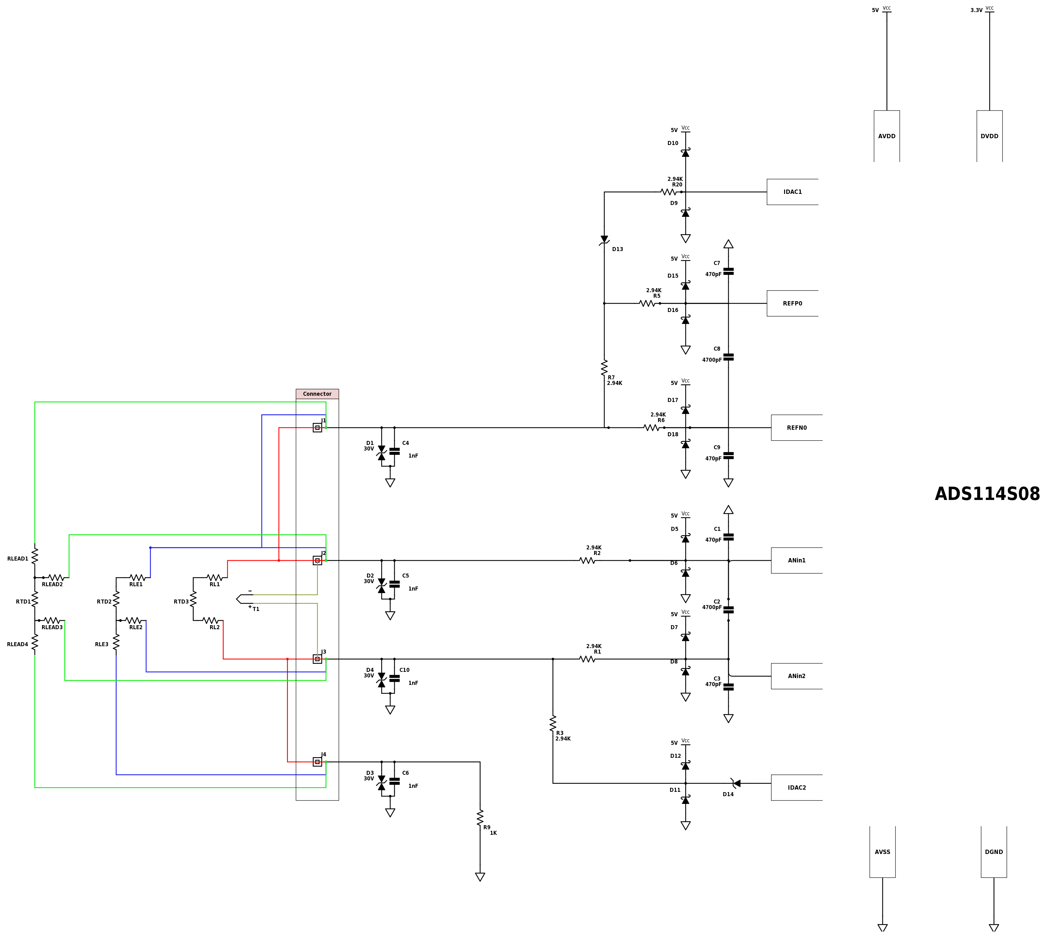
1.The IDAC2 source will remain connected even if it is not needed but I will disable it from the internal ADC mux, I am not sure if that will cause any problem?
Is it better to have an external jumper to wire the IDAC2 source when 3-wire RTD used?
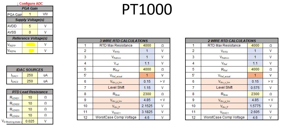
2. I would like to ask about the ADS114S08 datasheet equations number 21 and 23, in equation 21 the lead resistance seems to be ignored while it was taken into account in equation 23.
In datasheet equation 21 is:
VAinN = (IDAC1 + IDAC2) RBIAS
However, I think it should be:
VAinN = IDAC2*RL2 + (IDAC1 + IDAC2) (RL3 + RBIAS)
For Equation 23 in data sheet:
VAinP = IDAC1(RL1 + RRTD) + VAinN
I think should be:
VAinP = IDAC1(RL1 + RRTD) + (VAinN / IDAC2*RL2)
Please correct me if my calculations are wrong.
3.Regarding to connecting a 2-wire or a 4-wire RTD, the data sheet didn’t show detailed calculations for that, and I didn’t find any TI document doing the calculations for high side reference. So I tried to do them myself.
2 Wire RTD:
VAinP = IDAC1(RL1 + RRTD + RL2 + RBIAS)
VAinN = IDAC1* RBIAS
To use the same RBIAS used for 3-wire RTD the IDAC1 current needs be doubled?
In this case the two lead resistors will get into the measurement, and I think I should subtract them out by software?
4 Wire RTD:
VAinP = IDAC1(RRTD + RL4 + RBIAS)
VAinN = IDAC1* (RBIAS + RL4)
To use the same RBIAS used 3-wire RTD the IDAC1 current needs be doubled.
In this case only RRTD is measured.
Please let me know if I should post this reply as a separate question.
Regards,
Mahmoud