This thread has been locked.

If you have a related question, please click the "Ask a related question" button in the top right corner. The newly created question will be automatically linked to this question.

DAC7750: Slew rate control feature not working

Part Number: DAC7750

Dear All,

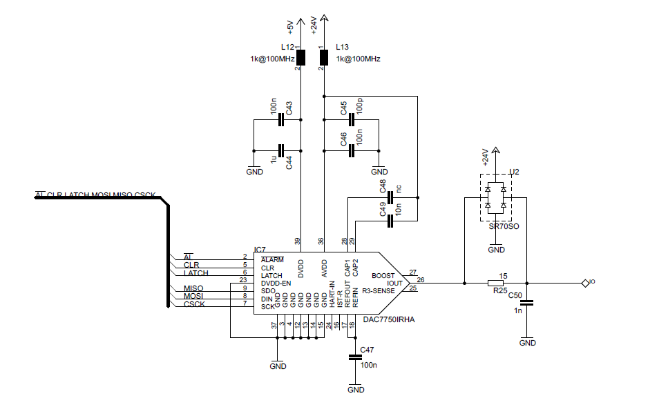
I'm using the DAC7750 converter in a design to output a 4-20mA signal with a update rate of 4kHz. I first implemented the basic feature (only DAC, no watchdog, no slew rate, no control, ...). After successful results I added some additional features like status read-back, watchdog, output open load check and slew rate control. Each feature works perfectly excepted the slew rate control. Actually as soon as I set the SREN bit of Control register the output freeze to 4mA. I tried various combinations of clock and step size but it has no effect. As soon as I clear the SREN bit then the output goes back to normal operation and varies between 4 and 20mA as expected. Please find below my DAC initialization code and schematic.

Thanks for helping me to enable the slew rate control that is necessary in my design.

Best regards

Julien
void DAC_Init(void){

    LATCH_Write(0);
    CLR_Write(1);
    CyDelayUs(1);
    CLR_Write(0); 
    
    DAC_Write(DAC_NOP, 0x00);   // Flush DAC shift register  
    
    DAC_Write(DAC_WRITE_CAL_GAIN, 0x8000);  // Set device calibration gain to 1.000
    DAC_Write(DAC_WRITE_CAL_ZERO, 0x0000);  // Set device calibration zero to 0.000    
    
    DAC_conf_reg.U16 = 0;
    
    DAC_conf_reg.bits.CALEN = 0;    // User calibration control
    DAC_conf_reg.bits.HARTEN = 0;   // HART interface control
    DAC_conf_reg.bits.CRCEN = 0;    // CRC control
    DAC_conf_reg.bits.WDEN = 1;     // Watchdog control
    DAC_conf_reg.bits.WDPD = 3;     // Watchdog period control
    
    DAC_Write(DAC_WRITE_CONF, DAC_conf_reg.U16);
    
    DAC_ctrl_reg.U16 = 0;
    
    DAC_ctrl_reg.bits.REXT = 0;     // Disable external sensing resistor
    DAC_ctrl_reg.bits.OUTEN = 1;    // Enable output
    DAC_ctrl_reg.bits.SRCLK = 0b1100;    // Slew rate clk control
    DAC_ctrl_reg.bits.SRSTEP = 0b111;   // Slew rate step control
    DAC_ctrl_reg.bits.SREN = 0;     // Slew rate enable
    DAC_ctrl_reg.bits.DCEN = 0;     // Daisy chain disable
    DAC_ctrl_reg.bits.RANGE = 0b101; // Set output range to 4...20mA
    
    
    DAC_Write(DAC_WRITE_CTRL, DAC_ctrl_reg.U16);
    
}

  • Howdy Julien and welcome to the e2e forums!

    Using the information you've provided I'm able to determine the following:

    • Slew Rate Update Clock : 6.9kHz
    • SRSTEP: 8LSB
    • RANGE: 4 to 20mA
    • SREN does show as '0', but I'm assuming you toggle this bit later in the program

    The benefits of the slew rate control feature are largely seen when the device is transitioning between large code values.  For instance in the case of a 4 to 20mA transition, and using the above information, you can calculate the slew time (for page 26 of the DS) as:

    Slew Time = (Output Change)/(Step Size x Update Clock Freq x LSB Size) = (0.16mA/(8LSB x 6.9kHz x 3.9uA)) = 74ms

    When the device slews from the zero-scale to full-scale, the DAC will increase the output by 8LSB at an update rate of 6.9kHz.  This will be seen as a stair case wave form similar to the ones shown on page 26.

    Since you writing to the DAC register at a much faster rate, 4kHz, you are not allowing the DAC output enough time to transition to the first "stair".  My intuition is that you will see better results if you increase the DAC update frequency (Hz) through "SRCLK" bits, or by reducing the program write frequency below 4kHz. 

    • Additionally, when writing to the DAC Registers at 4kHz, what is the typical delta (code jump - LSBs) from the previous code?
    • Is the delta between DAC Register writes a few LSBs or larger?

    Information to these questions will help with understanding the issue.

    Best Regards,

    Matt

  • Hi Matt,

    Thanks for your quick reply.
    Actually the code above is a "screenshot" of the last configuration variant I did where I actually disabled the slew rate to make the output work again.
    I understand your point of view about the 74ms slew rate that is not well suited for a 4kHz update rate. But again this specific clock and step size is only one of the configuration variant I tried. I also tried the maximum clock (258kHz) to ensure that the DAC has enough time to step but the result is always the same : the output is fixed to 4mA. How to explain this frozen output ? As far as I understand the datasheet, even with a bad clock and step size the output will anyway change more or less slowly... isn't it ? Is the slew rate control limited to be used with low update rate (i.e. some Hz) ?

    To reply to your question:
    - The typical delta is a few LSB, the typical output signal is a sinus at 100-300Hz with about 4mA amplitude peak-peak

    Best regards
    Julien
  • Hi Julien,

    Can you provide the information asked in the bullets below?  Additionally, in parallel I may use the EVM to see if I'm able to create a situation were I get similar results to the one you've posted.

    • Can you provide a register readback on the Configuration register?
    • Can you probe the /ALARM pin, and also verify the status of the CLR input signal?
    • Additionally, changing the RANGE bits at any time in the program will clear the DAC data register.  Therefore it's important to set the range only once, which is probably what you are doing, but it's good to check all bases.

    Best Regards,

    Matt

  • Hi Matt,

    Thanks for your continuous support. Please find my answer below:

    • Readback from configuration register: Yes I checked by means of reading back the value of each configuration register and it contains what it has to
    • Alarm pin: I checked the state of this pin and it is conform to the status register: it is "1" when everything is OK and it goes to "0" when I disconnect the load from the DAC output for instance
    • I never change the RANGE excepted in the initialization sequence shown above...

    To give you more information, please find below the access to the DAC in my application in an interrupt-triggered 4kHz loop:

    [...]

        DAC_Write(DAC_WRITE_DAC, (uint16)(T_object * DAC_cst));
        
        if(cnt++ > 800){
            cnt = 0;  
            DAC_STATUS = DAC_Read(DAC_READ_STS);
            TMP1 = DAC_Read(DAC_READ_CTRL);
            DAC_Reset_WTD();
        }

    [...]

    The initialization of the DAC is called only once at the start-up of the system.

    Best regards

    Julien

  • Hi Julien,

    Thank you for the information, we will apply it to our debug.  I do have a few follow-up questions I was hoping you could answer:

    • Can you provide the readback value of the configuration register?  And if possible, verify the DAC Data register changes when writing to the device.
    • Additionally, can you perform the experiment below:
      • Set SRSTEP to "100" (1 LSB)
      • Set SRCLK to "0000" 258kHz
      • Enable Slew rate
      • Write to DAC @ 4kHz
      • Measure output with oscilloscope
      • Through the above setup, the maximum code delta between the newly written and older code must be 64 LSBs or fewer.  Anything above this code change may result in improper settling.  

    • Additionally, a simple check may also determine if the device is capable of slewing for your current configuration.  Maybe from a code near zero-scale to a code near full-scale, with the original SRSTEP (8 LSB) and SRCLK (6.9kHz) and verify if you do see a staircase transition on the output when reaching the second code. 
    • The next step is recreating the issue in the lab, which I hope to accomplish by the beginning of next week.

    Best Regards,

    Matt

  • Dear Matt,

    I made the experiment you requested in your previous message. Please find the code and results below:

    1) Initialization code:

    void DAC_Init(void){
    
        LATCH_Write(0);
        CLR_Write(1);
        CyDelayUs(1);
        CLR_Write(0); 
        
        DAC_Write(DAC_NOP, 0x00);   // Flush DAC shift register  
        
        DAC_Write(DAC_WRITE_CAL_GAIN, 0x8000);  // Set device calibration gain to 1.000
        DAC_Write(DAC_WRITE_CAL_ZERO, 0x0000);  // Set device calibration zero to 0.000    
        
        DAC_conf_reg.U16 = 0;
        
        DAC_conf_reg.bits.CALEN = 0;    // User calibration control
        DAC_conf_reg.bits.HARTEN = 0;   // HART interface control
        DAC_conf_reg.bits.CRCEN = 0;    // CRC control
        DAC_conf_reg.bits.WDEN = 1;     // Watchdog control
        DAC_conf_reg.bits.WDPD = 3;     // Watchdog period control
        
        DAC_Write(DAC_WRITE_CONF, DAC_conf_reg.U16);
        
        DAC_ctrl_reg.U16 = 0;
        
        DAC_ctrl_reg.bits.REXT = 0;     // Disable external sensing resistor
        DAC_ctrl_reg.bits.OUTEN = 1;    // Enable output
        DAC_ctrl_reg.bits.SRCLK = 0b0000;    // Slew rate clk control
        DAC_ctrl_reg.bits.SRSTEP = 0b100;   // Slew rate step control
        DAC_ctrl_reg.bits.SREN = 1;     // Slew rate enable
        DAC_ctrl_reg.bits.DCEN = 0;     // Daisy chain disable
        DAC_ctrl_reg.bits.RANGE = 0b101; // Set output range to 4...20mA
        
        
        DAC_Write(DAC_WRITE_CTRL, DAC_ctrl_reg.U16);
        
    }

    2) Test loop

        //CyGlobalIntEnable; /* Disable global interrupts. */
        
        while(1){
        DAC_Write(DAC_WRITE_DAC, 0);
        CyDelay(100);   // Delay 100ms
        DAC_Write(DAC_WRITE_DAC, 0xffff);
        CyDelay(100);   // Delay 100ms
        }

    The output is measured across a 100R resistor:

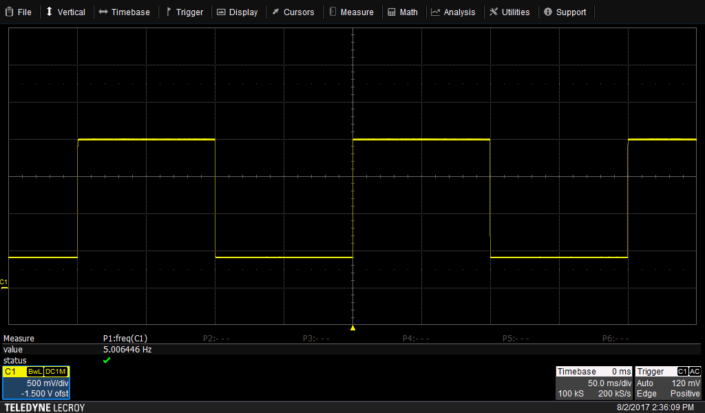
    Result with SREN = 1

    Result  with SREN = 0

    As you can see in the result above, we still have the same behaviour: as soon as SREN=1 then the output freeze to 4mA while clearing SREN make the DAC working as expected.

    Additionnaly I check the DAC register by read back means and the content is always 0 while SREN = 1. It is like if the DAC register becomes "read-only" when the SREN bit is set. What do you think about this ?

    Best regards

    Julien

  • Hi Julien,

    Thank you for the information. I've additionally confirmed with colleagues that the information and procedure in your post seems to be correct, however, we may need more information to verify that configurations are being set correctly through code.

    Can you send us a scope capture of the SPI command that enables SR control?
    Additionally, can you readback the configuration register after the init sequence in your code? Please provide this data in hexadecimal format.

    Best Regards,
    Matt
  • Dear Matt,

    Please find below the recorded data from my logic analyzer. You can download for free the reading software to the following link:

    Viewing software:

    Raw data:

    logic_analyser_capture.rar

    First open the setup file and then open the data file to have the right data view.

    Additionally, while doing these capture I observed that is I apply the configuration code twice then the DAC starts working properly, even with the slew rate control. May be I have a timing mismatch or something like this.

    Thanks for your support again

    Julien

  • Hi Julien,

    It does sound like it may be a register sequence issue. Can you give more insight into the method that creates correct response with slew rate control? In the meantime, I'll look into your files and will hope to have more feedback before the end of this week.

    Best Regards,
    Matt