This thread has been locked.

If you have a related question, please click the "Ask a related question" button in the top right corner. The newly created question will be automatically linked to this question.

ADC12J4000: SYSREF LVPECL DC-coupled swing value - datasheet VS Hyperlynx IBS simulation

Part Number: ADC12J4000

Hi,

I'm would like to use a dc coupled line and the LVPECL standard for the communication around the ADC12J4000.

I've got some questions around the voltage values of the datasheet.

These values are shown here :

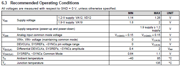
So, the common mode voltage has to be somewhere between 0VDC and 1.9VDC, and the differential swing between 0.4Vpp and 2Vpp.

First question : are those differential values |SYSREF+ - SYSREF-| ?

If it is, that would mean the minimum required single ended voltage swing is 0.4/2=0.2Vpp, meaning the single ended minimum values to be +/-0.1V.

I downloaded the ADC12J4000's IBS file, and simulated it being driven by the AD HMC7044 :

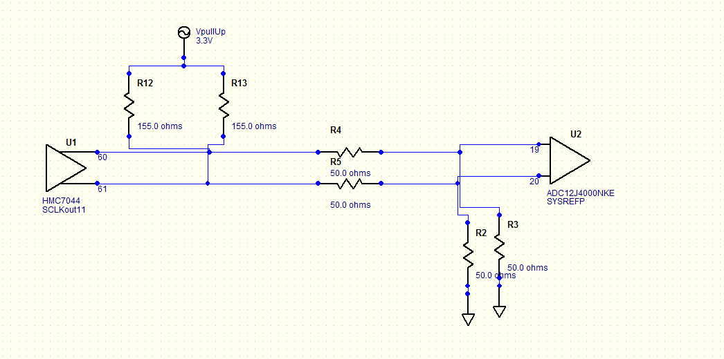
As the HMC7044's LVPECL's output common mode voltage is 2VDC, I tried to lower it to 1VDC with thoses resistors, keeping the 50R adaptation.

The results are shown here :

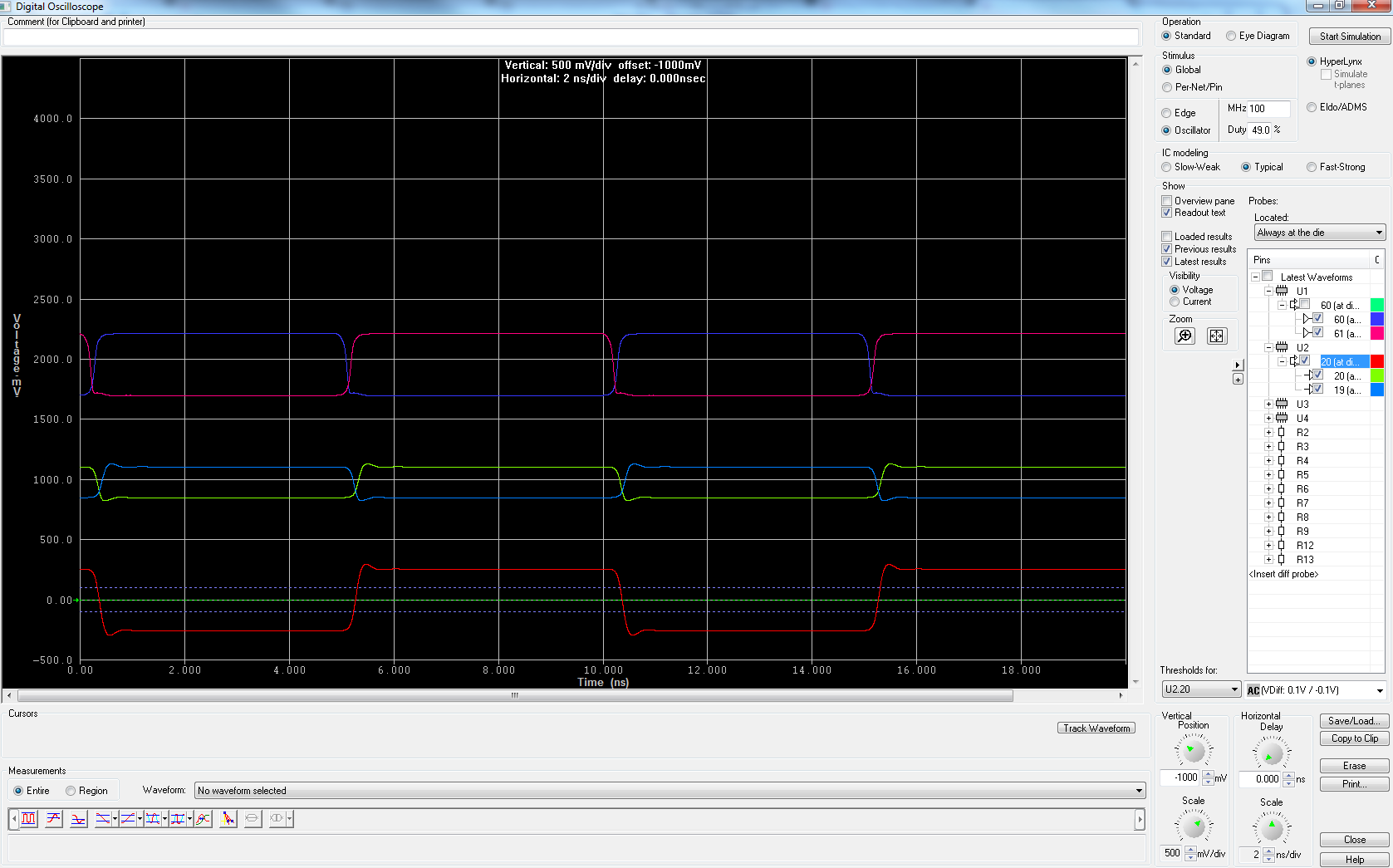
You've got the HMC7044's output on top, the ADC12J4000's input in the middle and the AC-coupled diff at the bottom, with the ADC's thresholds.

In the bottom right hand corner, you can see AC-coupled differential thresholds for the ADC12J4000 being +/-0.1V.

That does not correspond to my previous calculations, as I stated the single ended minimum swing should be +/-0.1V ...

If the IBS model is right, as the differential value received by the ADC12J4000 (red line in the simulation's output) is superior to the IBS threshold of the ADC, my application should be working.

If the IBS model is wrong and the real thresholds are +/-0.2V (as I understand the datasheet), my application might not work because my differential amplitude is just superior to 0.4Vpp, and I would like to have at least 150mVpp of margin.

Second question : are my previous calculations right ? If it is, is the IBS model wrong ?

Third question : Are the thresholds the same for both AC-coupled and DC-coupled modes ?

Thanks for reading, have a good day

Alexis

  • Hi Alex,

    We are looking into your question. We will reply as soon as we can.

    Regards,
    Neeraj
  • Hi Alex,

    I think you are mixing common mode voltages. As shown in table 6.3. Vcmi (Analog input common mode voltage) is common mode voltage that should be applied to analog input of the ADC and it applicable for pins VIN+ and VIN- .

    Where the following row of the table describes what voltage can be applied at those pins.

    The following row about difference voltage for DEVCLK, SYSREF and SYNC. which means differential voltage(SYSREF+ - SYSREF- )for following signal should be between 0.4Vpp for 2Vpp so min single ended min swing should be 0.2V not 0.1V.

    Lastly as shown below Vcm is common mode voltage that should be maintained  for SYREF and SYNC signals.

    Yes thresholds for AC and DC are same.

    Regards,

    Neeraj Gill

  • Hello,

    thanks for  your answer !

    You are absolutely right, I made a mistake for the common mode voltage.

    I took the right value when I did the simulation but just wrote too fast my message here, that's why the simulation has a common mode voltage of 1VDC and my message mentioned a 1.9VDC common mode voltage.

    Neeraj Gill said:

    The following row about difference voltage for DEVCLK, SYSREF and SYNC. which means differential voltage(SYSREF+ - SYSREF- )for following signal should be between 0.4Vpp for 2Vpp so min single ended min swing should be 0.2V not 0.1V.

    That's exactly what I meant ! The single ended signal should be 200mVpp, so it can be described as [Common mode voltage +/- 100mV].

    What I asked is that in Hyperlynx, the IBS file of the ADC12J4000 mentions the thresholds like this : "AC : Vdiff +/-0.1V"

    Two possibilities can be considered :

    _ This threshold describes the single ended value and match my calculations (and yours, that I quoted) : my application can be working but the simulation shows the singled ended input signal is just +/-100mV, which worries me a little...

    _ This thresholds describes the differential value and hence not match any of our calculations, and my application will work for sure as I have a differential amplitude which is twice the threshold.

    So there is a problem somewhere, and I would like to know whether I should trust our maths (the datasheet) or the IBS file ?

    Thanks,

    Alexis

  • Hi Alexis

    I have reviewed the details of the product datasheet, IBIS file and the IBIS standard description of vdiff. Based on what I have found I believe the vdiff spec in the ADC12J4000 IBIS file should be 0.2 instead of 0.1 to align to the 0.4Vpp minimum amplitude spec in the product datasheet.

    I will work with the modeling team to update the IBIS file accordingly.

    Best regards,

    Jim B