Part Number: ADC128S102
Hi
My customer need help with ADC128S102.
Because of each ADC input from 16by1 MUX, there are 16 analog input changing for each DIN.

When DIN is changed, the only first digital out is not correctly worked.
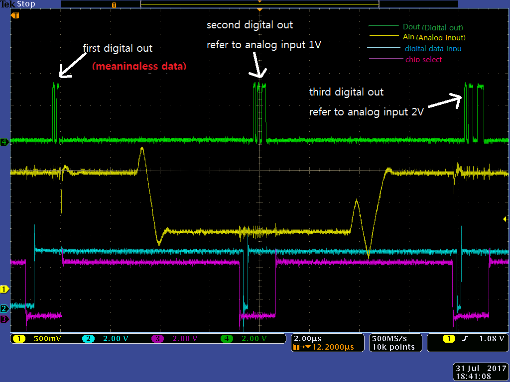
Please review an attached file. You can see control signals,analog inpu and digital output after changing from DIN(0, 0, 0) to (0, 0, 1).
- Analog input : IN1 (data changing: 2V, 1V, 2V)
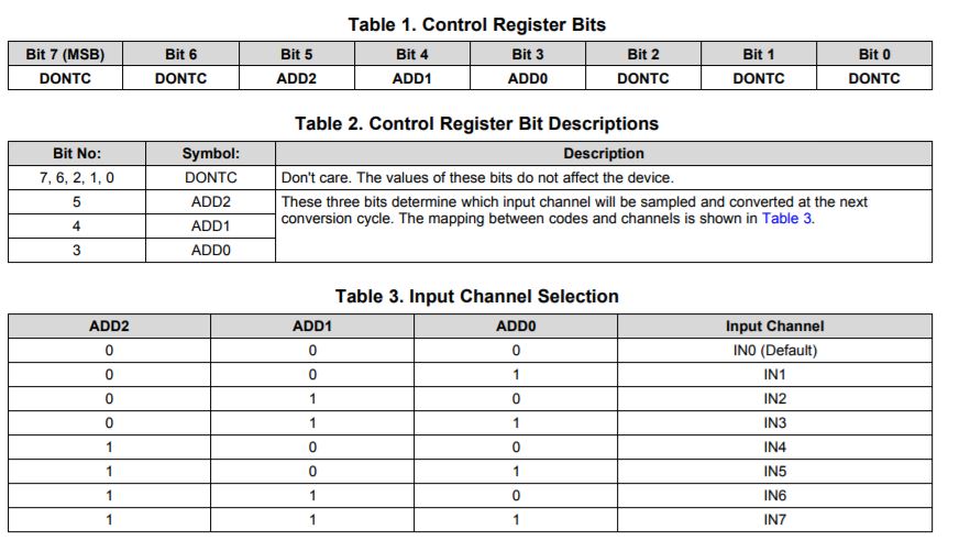
- digital data input : DIN (=> 0,0,1), for A/D of the second analog input channel.
- SCLK : 11.5MHz (not displayed on the file.
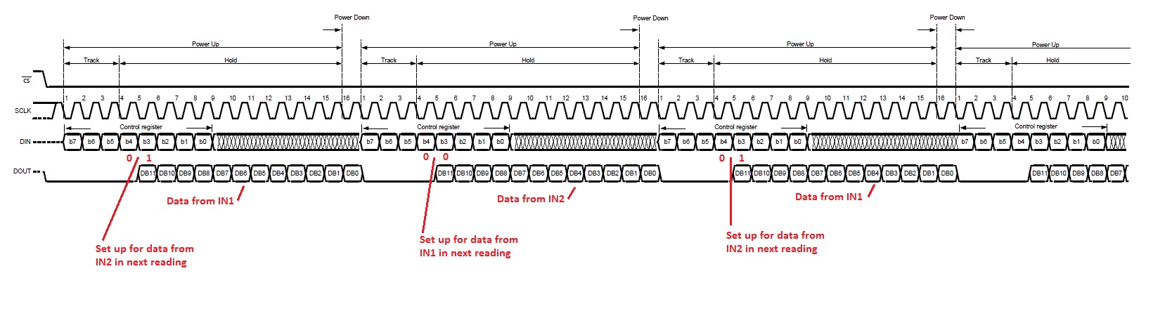
I set DIN like below datasheet after chip selector'falling.
The first digital out is for analog 2V but it is not. It is always about digit 10 regardless of input changing.
The second out is refer to analog input 1V.
And third out is refer to analog input 2V.
When I change DIN, I always get meaningless first digital out.
During same DIN, the 2nd, 3rd, 4th, ..., are changed refer to changed analog input.
I think that there is some wrong control when DIN is changed. But I can not find. Could make me clear this problem?

Waiting for your reply.
thanks
Star