This thread has been locked.

If you have a related question, please click the "Ask a related question" button in the top right corner. The newly created question will be automatically linked to this question.

ADS52J90EVM: Issues with configuration (using the TSW14J56EVM)

Part Number: ADS52J90EVM
Other Parts Discussed in Thread: ADS52J90

Dear all,

I am having a few difficulties in setting up the two EVMs in order to detect a sample frequency given via function generator. In HSDCpro, I have downloaded the appropriate firmware and have selected the ADS EVM as my main ADC for capture. For inputs, I am using a 5 MHz square wave for a clock (J75) and a 100 kHz sinusoidal wave as my test function in pin (SMA_CH4). When I try to capture this data, I get a message seen pictured here:

I took a look at the TSW board and currently the D4 LED is unlit and the D3 is still ON. I made sure everything was reconnected and not reset (as seen in the first suggestion) and am looking for a bit of help in order to give a custom sample (I am very new to FPGA programming and configuration so I need all the assistance I can get). 

Is there anyone who can help? It would be much appreciated since I have a very limited amount of time to get test samples running.

Thanks,

Christopher Harness
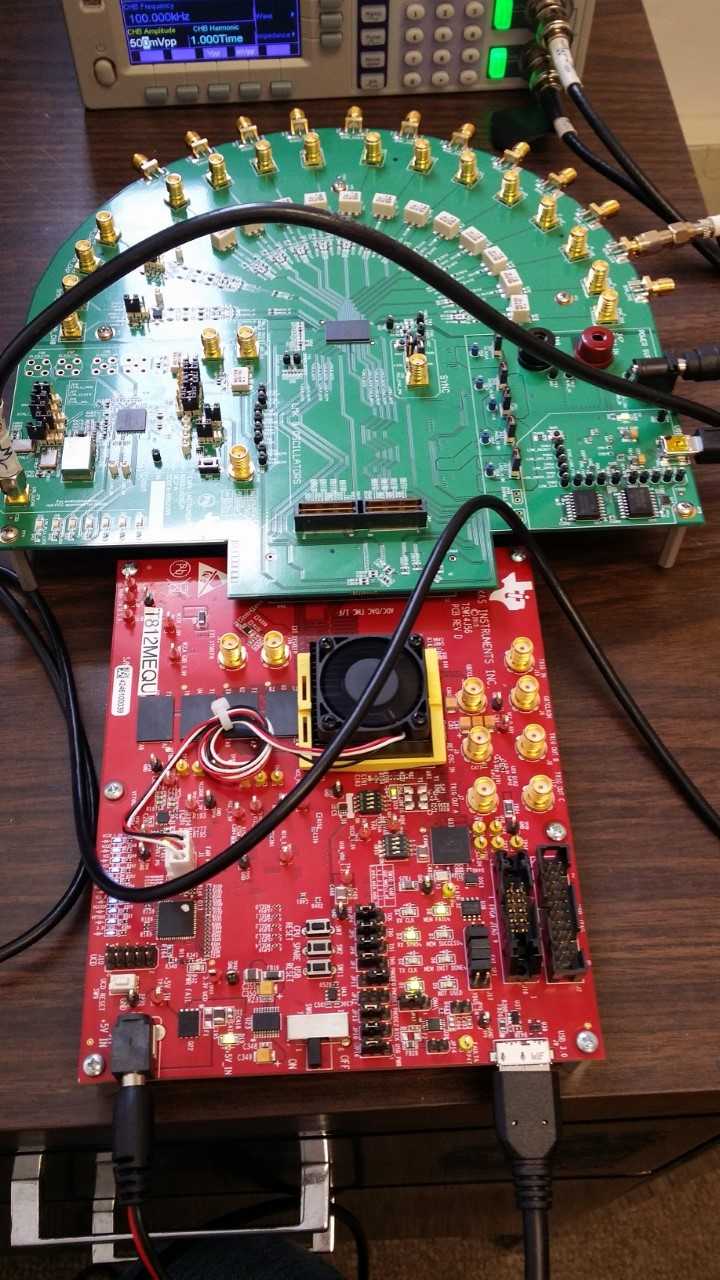
Also, is it known as to whether or not the TSW EVM series contain internal clocks, thus eliminating the use of external ones? If so, how is that configured or utilized?

  • Hi Christopher,

    The ADS52J90EVM has options to either take an external clock or use its onboard PLLs and crystals for clock generation.
    Since the EVM and user guide is setup to use an external clock by default, I recommend you start out with that.

    What JESD script are you running on the ADS52J90's GUI? Let us start with the 16x_14b_4ADC/Lane mode.
    The external clock for this configuration actually sends the input clock directly to the TSW14J56revD board and sends a divided clock to the ADS52J90 (divided by 4). Please try a higher input clock frequency (say 40MHz) and share your results.

    Also make sure each board has a power supply that can supply at least 2A.

    Sincerely,
    Olu

  • I do wish to give a quick update.

    While I have solved some of the initial issues in terms of scripting, I have run into a few more errors in terms of identification and accurately reconstructing a sample signal. To first mention, I am supplying both EVMs with +5.0 V of voltage; however, for the ADS EVM it is generating a current of .54 A and the TSW at 1.28 A. Should I increase voltage levels since I am unable to increase current given the model of my power supplies?

    In HMC-DAQ, I do get a configuration error after I initialize the device saying:
    "Error 5000 occurred at Notifier Timed Out; This error code is unidentified, etc."

    Even though I continue on, when I capture data in HSDCpro (with or without using an external clock in the ADS EVM), I get random noise instead of the arbitrary signal I wish to reconstruct. Based on what I originally posted and what I'm saying now, what are some steps I should consider taking to help produce accurate data and continue to use this device for other projects?

    ***ADDITIONAL INFORMATION***

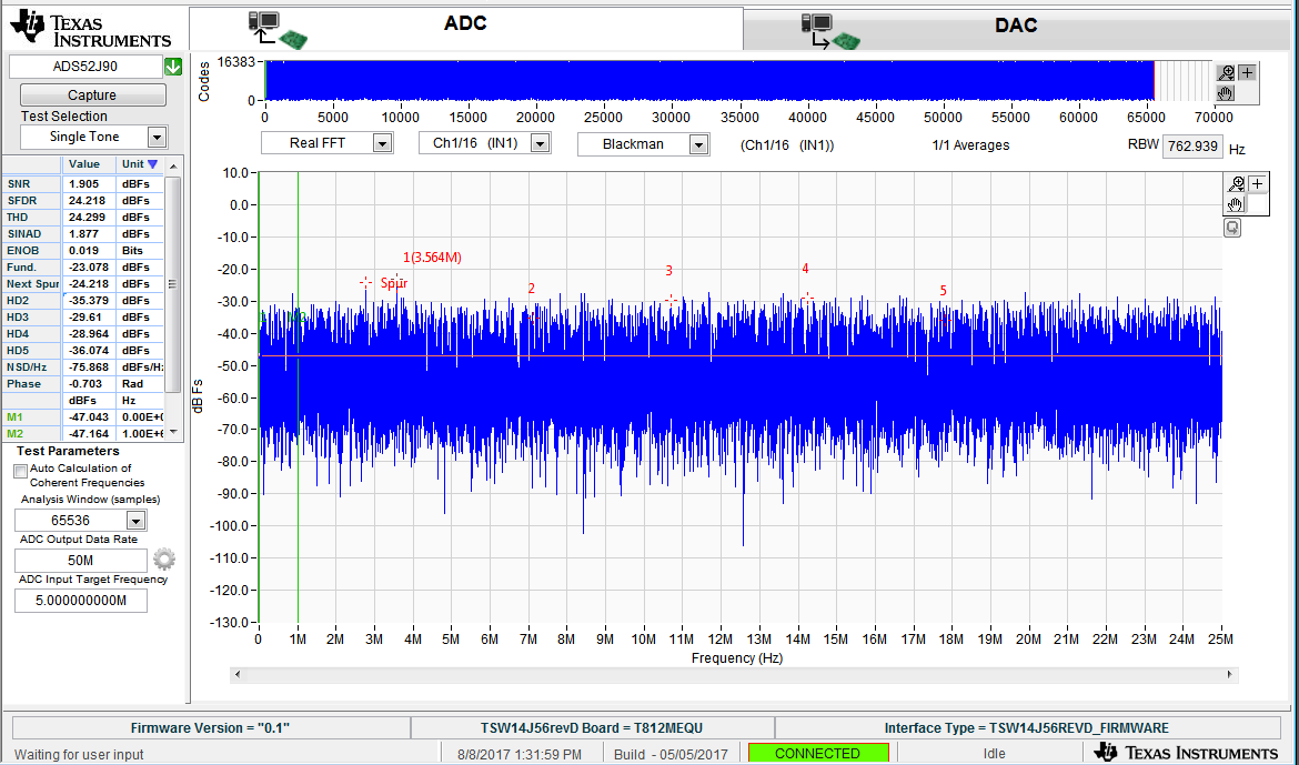
    This is the results I get at 1 MHz of a sinusoidal wave. This only occurs when I have an external clock in use since an internal clock cannot be accessed for the TSW and would like a bit of help on that configuration after reading the User's Manual. 

  • Hi Lawrence,

    You did not answer any of my questions. If you are using the 16x_14b_4ADC mode in HMC-DAQ GUI, you need to provide a clock frequency to J75 that is 4X your desired ADC sampling frequency.
    Also, does each EVM have a separate 5V, 2A power supply(you cannot increase voltage to compensate for current) and what is the state of the LEDs on the TSW1400EVM?

    Sincerely,
    Olu
  • Sorry about not responding to the first, yes I have been using that option, which resulted in the noise result shown above. Our clock is only able to go up to 5 MHz, so I've been testing smaller frequencies at around 500 kHz or lower. I use two power supplies for both EVMs, each able to generate up to 5 A; however, when I set it to 5 V it could only generate currents up to 1.3 and .6 A. As for the LEDs, nothing''s changed. Only LED D1,D3, and D8 light up no matter what firmware package is installed and will not change regardless.
    My last question is, you mention that one of these EVMs contain a built--in clock. How do I access it, program it, and what is its highest sampling frequency?
    Thanks
  •  Also, this was the result I obtained from a recent EyeQ Scan; however, I am not sure what this tells me. Allow me to clarify that this is the first FPGA/EVM DAQ I have ever worked on.

  • Hi Lawrence,

    You definitely need an LMK clock input higher than 10MHz. To use the onboard 40MHz clock on the ADS52J90EVM as the LMK's clock input, connect pin 1 to 2 on JP6, pin 2 to 3 on JP8 and pin 2 to 3 on JP7.
    You should be able to observe a 40MHz signal at JP7 using an oscilloscope.

    Sincerely,
    Olu