This thread has been locked.

If you have a related question, please click the "Ask a related question" button in the top right corner. The newly created question will be automatically linked to this question.

ADS1252: Help check ADS1252 code

Part Number: ADS1252

Hi

Read the value from ADS1252, the values change in rules. The CLK is 9M.

Please help check the following code:

u32  ADS1252_Red(void)
{
   u32 recevice=0,i=0;
   while(ADS1252_Out==1);
   while(ADS1252_Out==0);
   while(ADS1252_Out==1);//t4
   while(ADS1252_Out==0);//t2
   while(ADS1252_Out==1);//t3
   ADS1252_SCLK=0;
   for(i=0;i<24;i  )
   {
       recevice<<1;
       ADS1252_SCLK=0;
       __NOP();
       __NOP();
       __NOP();
      ADS1252_SCKK=1;
      Delay_us(1);
     if(ADS1252_Out==1)
          recevice  ;
   }
   ADS1252_SCLK=0;
   Return recevice;

Thanks

Star

  • Hi Star,

    Which microcontroller are you using? Are you able to take advantage of a SPI peripheral and GPIO interrupt to communicate with the device?

    Most microcontrollers provide these peripherals. I would generally try to avoid using while loops for DRDY detection and bit banging the SPI communication, as those methods don't give you much control over timing and can be very prone to errors.

    Best regards,
    Chris

  • Hello,
    In accordance with the programme provided by the support, after implementation. At present the stability is no problem, but the actual measurement accuracy has changed, the input voltage changes 4mV, and the ADC152 change is 4uv.
    The actual test data are as follows:

    Input voltage ADC sampling voltage
    73.6mV 0.068069
    73.0mV 0.068069
    72.7mV 0.068069
    71.9mV 0.068069
    71.4mV 0.068069
    69.8mV 0.068065
    I don't know what the reason is. I hope I can get your help.
  • Hello,
    In accordance with the programme provided by the support, after implementation. At present the stability is no problem, but the actual measurement accuracy has changed, the input voltage changes 4mV, and the ADC152 change is 4uv.
    The actual test data are as follows:
    Input voltage ADC sampling voltage
    73.6mV 0.068069
    73.0mV 0.068069
    72.7mV 0.068069
    71.9mV 0.068069
    71.4mV 0.068069
    69.8mV 0.068065
    I don't know what the reason is. I hope I can get your help.
  • Hi user1212282,

    Would it be possible to see the raw ADC bytes for each measurement (before converting them to a voltage value)?
    Some times we can spot errors more easily when looking at the raw data format and we can check for errors in the math.

    Have you looked at the SPI communication with an oscilloscope?
    This can help you catch timing errors and ensure that the data you've captured truly matches the data output from the ADC, in case of errors in the C code that are not returning the data correctly.

    Also, if you could also share a schematic and let me know what you're using for the signal and reference voltage source that would helpful to me!

    Thanks,
    Chris

  • Hi Chris

    Thanks for your reply.

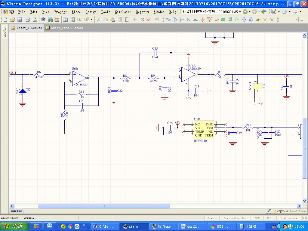
    Attached the schematic for your reference. 

    Waiting for your reply.

    Thanks

    Star

  • Hi Star,

    Thanks for the schematic!

    I don't see any issues related to the circuit. I think the problem is likely a software issue. Would it be possible to see the raw ADC codes and perhaps also the code used to convert from codes to voltage?

    Best Regards,
    Chris