This thread has been locked.

If you have a related question, please click the "Ask a related question" button in the top right corner. The newly created question will be automatically linked to this question.

ADS124S08EVM: Delta Sigma EvaluaTIon Software: Scripting for repetitive functions

Part Number: ADS124S08EVM
Other Parts Discussed in Thread: ADS124S08, ADS114S08

Hi, I am evaluating the ADS124S08 with a wheatstone bridge, and want to study the affects of turning on the excitation current with respect to accuracy of the sensor (self heating) at various excitation currents and various periods of time.  I want to mimic a low power mode, where the system wakes up, takes 1 or more measurements, falls asleep for a specific period of time, then repeats.  I want to set up the scripts to do:

1) Turn on the Low side drive (ADSS-SW).  

2) Enable IDAC1 to a specified current

3) Take several measurements at specified sample rate (want to vary the sample rate), (see when the system stabilizes)

4) Turn off ADSS-SW (And maybe IDAC???)

5) Go into the sleep mode

6) Repeat

I (think) I won't have trouble doing 1-5 with a custom scripts.  However, 2 things I am not clear about is 1) How to do this repetitively (do I just have to repeat several times by repeating the command sequence several times within the scripts , and 2) how to record and view the results (using Data Analysis?)

I am a little confused how the Data Analysis interacts with the main software.  What I mean is.... My normal operation is to select a script (user or Predefined), then press run.  Then go to the Data Analysis tool, select number of samples, and click collect data.  My understanding is that the ADS124S08 is just free running, and by clicking "Collect Data", you are just recording the data that is already being output from the ADS.  However, in the scenario described above, the ADC will be starting and stopping.  Will collecting and viewing the data even work when the ADS is sleeping and waking up?   

Lastly, I saw some discussion on another thread how the Delta-Sigma EvaluaTIon software was going away and getting replaced.  When is the expected replacement coming?  Do you need beta testers?

  • HI Scott,

    Thanks for your interest in the ADS124S08.  Just this morning I was discussing with a colleague how this might be done, so I find it interesting that have asked this question.  Currently we do not have a looping feature.  As you mentioned, you would have to repeat a series of sequences.  You can do this manually in the script editor, or you could find a desired script file and edit the contents in a text editor using cut and paste.  Save the new script file in the User folder.

    That was the easy part.  What is most difficult is the capturing of data.  You could use the READDATA command within the script, and you will get a return value of one conversion result.  It is possible to use the COLLECTSETUP and COLLECT command to a capture larger sequence of results, but currently there is no way automatically capturing that data to a file.  The data will be displayed in the Console tab if the Console tab is enabled (by selecting 'Enable Console tab in main display' in File -> Options.  The data is sent to the console, but must be interpreted correctly.  Here the biggest issue is there is no cut/paste ability from Console window.  So in my opinion this is worthless as this would be a totally manual operation and prone to error in transcription.

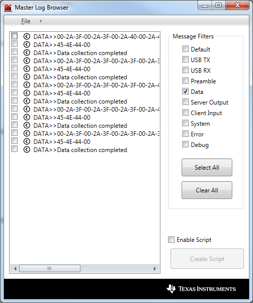
    There is one other possible option that may work, but I've had some issues from time to time while saving data to a file.  The communication from the GUI to the EVM (and vice versa) is handled as USB bulk transfers.  The GUI parses the data and sends the data acting as a server to the analysis client.  The raw data coming from the USB can be captured in the Master Log file which can be saved.  The Master Log can be accessed from File -> Master Log Browser.  To avoid program crashing and to more easily view the data, clear all Message Filters, then select Data.  Then save the data to a file.  The selection window should be as shown below:

    The data captured can be saved to a text file that can be parsed and analyzed. The above data is shown from a capture of data sent from the ADS114S08 which is 16-bit.  Each conversion result is prefixed by '00' followed by 2 bytes of data for the ADS114S08.  There would be 3 bytes returned for the ADS124S08.  If STATUS or CRC is enabled, this data will also be transmitted, so care must be taken regarding which results you are using.  When the collection is complete, the firmware tells the GUI it is finished by sending ASCII 'END'.  This is a bit cumbersome but can work.

    Regarding the new GUI, this is expected sometime in the fall.  We will try to keep you posted on developments for both the current and new GUI.

    Best regards,

    Bob B

  • Hi Scott,

    just a quick comment regarding your implementation. You don't necessarily need to control both the IDACs and low-side switch to power the bridge up and down. You can use either method.
    Means either leave the IDAC on all the time and control the bridge excitation using the switch, or leave the switch closed all the time (or better don't use it at all) and turn the IDAC on and off.

    Regards,
  • Thanks Bob.  I will get busy massaging the scripts to create the experiment that I desire, and read the data as you mention above.  

    The translation from hex numbers into "counts" is just a direct conversion between hex and dec, using unsigned hex, i.e. where 0000 through FFFF = 0 through 65535, and 000000 through 0xFFFFFF is 0 to 16777215.  Correct?

    I look forward to seeing the new software.  Hopefully it can address some of these workarounds.

    Thanks for your detailed help!

  • Regarding the IDAC, in my real application, I plan to put the ADC into POWERDOWN mode, which turns off both the IDAC and the low-side switch. I wanted to test to see what kind of real power consumption I got in mixed mode (wakeup, take a reading(s), fall asleep). So I'll test using the SLEEP command. I don't see a description on the SLEEP command, however, but I assume I just use the SLEEP, then Delay xx, then WAKE. I'll actually try this this afternoon, assuming I can actually do some engineering work and stop doing paperwork LOL!
  • Hi Scott,

    the ADS124S08 does actually not offer a SLEEP command, only a POWERDOWN command.
    You would send the POWERDOWN command, delay for x seconds and then send the WAKEUP command.

    I will let Bob comment on your code conversion question.

    Regards,
  • Thanks Joachim, sorry, I was using the SLEEP nomenclature in the Evaluation Software, which I presume is the same as the POWERDOWN command in the datasheet? (could you please confirm, as there is no documentation of the SLEEP command in the eval software that I can find).
  • So I reused the Bridge Measurement predefined script, and created my own version that I saved in the user scripts section.  I tested this incrementally.  First I added a DELAY 500 and a READDATA command after the last command in the original script, which is SFOCAL (all commands henceforth is using the eval software nomenclature).  This read back the correct reading from my attached bridge.  Then I copied all the lines of the script and pasted after the last READDATA  command (except for PAUSE), and saw the appropriate two READDATA samples.  Then I added a few more READDATA commands after the original READDATA commands, with DELAY 50 between and got correct readings.  Then in the middle of the script, right after the READDATA commands, I inserted a SLEEP command, followed by DELAY 2000, then a WAKE command, then DELAY 2000.  That's where I started having issues.  In theory I should have seen the same results as I did before (but with data slightly fluctuating, of course), but #1 the register contents are different, and #2, the data reads zero. If I enter the Console, then issue a READDATA command, it returns exactly zero every time. I have to power down the eval board (unplug from computer), issue a reset on the script, and then run the script again for READDATA to read correctly (whether in the console, or as part of a script). Here are the files one with the sleep and wakeup, and the other without:

    <?xml version="1.0" encoding="utf-8"?>
    <script>
      <name>Bridge - User with sleep</name>
      <description>This script sets up a bridge measurement by selecting the REF0 reference and setting the PGA to 128.  Input is connected to AIN8 and AIN9 and data rate set to 20sps.</description>
      <command_list>
        <command>
          <command_string>PAUSE</command_string>
          <description>Set JP9 so that AVDD is powered by 5V.  Connect JP8 jumper to AVDD (2-3), and JP11 to SW (1-2).  Connect bridge sensor to terminal block J8. Pin 1 connects to EXC+ (RP0), pin 2 to IN+ (A8), pin 3 to IN- (A9) and pin 4 to EXC- (RN0).  </description>
        </command>
        <command>
          <command_string>WREG 05 30</command_string>
          <description>Use the REF0 input pair and reference buffers disabled</description>
        </command>
        <command>
          <command_string>WREG 03 0F</command_string>
          <description>PGA is enabled and gain set to 128</description>
        </command>
        <command>
          <command_string>WREG 02 89</command_string>
          <description>Set mux input pair to AIN8/AIN9</description>
        </command>
        <command>
          <command_string>WREG 04 14</command_string>
          <description>Set the data rate to 20sps</description>
        </command>
        <command>
          <command_string>WREG 09 10</command_string>
          <description>Set SYS_MON to normal input mode</description>
        </command>
        <command>
          <command_string>REGMAP</command_string>
          <description>Read back the register settings</description>
        </command>
        <command>
          <command_string>DELAY 500</command_string>
          <description>Delay to make sure register readback is complete</description>
        </command>
        <command>
          <command_string>HOLDSTART 1</command_string>
          <description>Set the START pin high for continuous conversions</description>
        </command>
        <command>
          <command_string>DELAY 500</command_string>
          <description>Delay to make sure register readback is complete</description>
        </command>
        <command>
          <command_string>SFOCAL</command_string>
          <description>Run the self offset calibration</description>
        </command>
        <command>
          <command_string>DELAY 500</command_string>
          <description>Wait some more for offset calibration to complete</description>
        </command>
        <command>
          <command_string>READDATA </command_string>
          <description />
        </command>
        <command>
          <command_string>DELAY 50</command_string>
          <description>Delay script execution...</description>
        </command>
        <command>
          <command_string>READDATA </command_string>
          <description />
        </command>
        <command>
          <command_string>DELAY 50</command_string>
          <description>Delay script execution...</description>
        </command>
        <command>
          <command_string>READDATA </command_string>
          <description />
        </command>
        <command>
          <command_string>DELAY 50</command_string>
          <description>Delay script execution...</description>
        </command>
        <command>
          <command_string>READDATA </command_string>
          <description />
        </command>
        <command>
          <command_string>DELAY 50</command_string>
          <description>Delay script execution...</description>
        </command>
        <command>
          <command_string>READDATA </command_string>
          <description />
        </command>
        <command>
          <command_string>SLEEP </command_string>
          <description />
        </command>
        <command>
          <command_string>DELAY 2000</command_string>
          <description>Wait some more for offset calibration to complete</description>
        </command>
        <command>
          <command_string>WAKE </command_string>
          <description />
        </command>
        <command>
          <command_string>DELAY 2000</command_string>
          <description />
        </command>
        <command>
          <command_string>WREG 05 30</command_string>
          <description>Use the REF0 input pair and reference buffers disabled</description>
        </command>
        <command>
          <command_string>WREG 03 0F</command_string>
          <description>PGA is enabled and gain set to 128</description>
        </command>
        <command>
          <command_string>WREG 02 89</command_string>
          <description>Set mux input pair to AIN8/AIN9</description>
        </command>
        <command>
          <command_string>WREG 04 14</command_string>
          <description>Set the data rate to 20sps</description>
        </command>
        <command>
          <command_string>WREG 09 10</command_string>
          <description>Set SYS_MON to normal input mode</description>
        </command>
        <command>
          <command_string>REGMAP</command_string>
          <description>Read back the register settings</description>
        </command>
        <command>
          <command_string>DELAY 500</command_string>
          <description>Delay to make sure register readback is complete</description>
        </command>
        <command>
          <command_string>HOLDSTART 1</command_string>
          <description>Set the START pin high for continuous conversions</description>
        </command>
        <command>
          <command_string>DELAY 500</command_string>
          <description>Delay to make sure register readback is complete</description>
        </command>
        <command>
          <command_string>SFOCAL</command_string>
          <description>Run the self offset calibration</description>
        </command>
        <command>
          <command_string>DELAY 1000</command_string>
          <description />
        </command>
        <command>
          <command_string>READDATA </command_string>
          <description />
        </command>
      </command_list>
    </script>
    <?xml version="1.0" encoding="utf-8"?>
    <script>
      <name>Bridge - User</name>
      <description>This script sets up a bridge measurement by selecting the REF0 reference and setting the PGA to 128.  Input is connected to AIN8 and AIN9 and data rate set to 20sps.</description>
      <command_list>
        <command>
          <command_string>PAUSE</command_string>
          <description>Set JP9 so that AVDD is powered by 5V.  Connect JP8 jumper to AVDD (2-3), and JP11 to SW (1-2).  Connect bridge sensor to terminal block J8. Pin 1 connects to EXC+ (RP0), pin 2 to IN+ (A8), pin 3 to IN- (A9) and pin 4 to EXC- (RN0).  </description>
        </command>
        <command>
          <command_string>WREG 05 30</command_string>
          <description>Use the REF0 input pair and reference buffers disabled</description>
        </command>
        <command>
          <command_string>WREG 03 0F</command_string>
          <description>PGA is enabled and gain set to 128</description>
        </command>
        <command>
          <command_string>WREG 02 89</command_string>
          <description>Set mux input pair to AIN8/AIN9</description>
        </command>
        <command>
          <command_string>WREG 04 14</command_string>
          <description>Set the data rate to 20sps</description>
        </command>
        <command>
          <command_string>WREG 09 10</command_string>
          <description>Set SYS_MON to normal input mode</description>
        </command>
        <command>
          <command_string>REGMAP</command_string>
          <description>Read back the register settings</description>
        </command>
        <command>
          <command_string>DELAY 500</command_string>
          <description>Delay to make sure register readback is complete</description>
        </command>
        <command>
          <command_string>HOLDSTART 1</command_string>
          <description>Set the START pin high for continuous conversions</description>
        </command>
        <command>
          <command_string>DELAY 500</command_string>
          <description>Delay to make sure register readback is complete</description>
        </command>
        <command>
          <command_string>SFOCAL</command_string>
          <description>Run the self offset calibration</description>
        </command>
        <command>
          <command_string>DELAY 500</command_string>
          <description>Wait some more for offset calibration to complete</description>
        </command>
        <command>
          <command_string>READDATA </command_string>
          <description />
        </command>
        <command>
          <command_string>DELAY 50</command_string>
          <description>Delay script execution...</description>
        </command>
        <command>
          <command_string>READDATA </command_string>
          <description />
        </command>
        <command>
          <command_string>DELAY 50</command_string>
          <description>Delay script execution...</description>
        </command>
        <command>
          <command_string>READDATA </command_string>
          <description />
        </command>
        <command>
          <command_string>DELAY 50</command_string>
          <description>Delay script execution...</description>
        </command>
        <command>
          <command_string>READDATA </command_string>
          <description />
        </command>
        <command>
          <command_string>DELAY 50</command_string>
          <description>Delay script execution...</description>
        </command>
        <command>
          <command_string>READDATA </command_string>
          <description />
        </command>
        <command>
          <command_string>WREG 05 30</command_string>
          <description>Use the REF0 input pair and reference buffers disabled</description>
        </command>
        <command>
          <command_string>WREG 03 0F</command_string>
          <description>PGA is enabled and gain set to 128</description>
        </command>
        <command>
          <command_string>WREG 02 89</command_string>
          <description>Set mux input pair to AIN8/AIN9</description>
        </command>
        <command>
          <command_string>WREG 04 14</command_string>
          <description>Set the data rate to 20sps</description>
        </command>
        <command>
          <command_string>WREG 09 10</command_string>
          <description>Set SYS_MON to normal input mode</description>
        </command>
        <command>
          <command_string>REGMAP</command_string>
          <description>Read back the register settings</description>
        </command>
        <command>
          <command_string>DELAY 500</command_string>
          <description>Delay to make sure register readback is complete</description>
        </command>
        <command>
          <command_string>HOLDSTART 1</command_string>
          <description>Set the START pin high for continuous conversions</description>
        </command>
        <command>
          <command_string>DELAY 500</command_string>
          <description>Delay to make sure register readback is complete</description>
        </command>
        <command>
          <command_string>SFOCAL</command_string>
          <description>Run the self offset calibration</description>
        </command>
        <command>
          <command_string>DELAY 1000</command_string>
          <description />
        </command>
        <command>
          <command_string>READDATA </command_string>
          <description />
        </command>
      </command_list>
    </script>

    The registers that are different are the offset calibration registers:

             1st time    2nd time

    0A    00             86

    0B    00             FE

    0C    00             FC            

  • As a followup to my last post, I wrote a script that follows the predefined bridge config script, with a READDATA command at the end, and then I tacked on a SLEEP command (in essence putting the device in sleep mode until the script is stopped (I think).  However, I still read 4.25V across J8 1 and 4.  I have all jumpers set at the default except I removed JP11.  Any reason why the voltage across J8 does not go to zero when I go into sleep mode?  The low side switch should be opening when going to sleep, causing the voltage to drop to zero.   I presume it is because I am not actually in sleep mode....

  • Hi Scott,

    Sorry for the delay as I was out of office yesterday and it has been taking me a long time to catch back up. I will go back through all your posts, but regarding this last one it may be possible that you have a Rev A version of the EVM (indicated on the back side of the EVM).  If so, there is a mistake that was made regarding the low-side switch on this version and the low-side switch is essentially bypassed.

    Best regards,

    Bob B

  • Hi Scott,

    First of all, let's go back to the results from READDATA.  Depending on the input, you could have codes returned that are either positive or negative.  Positive codes returned range from 0x00 to 0x7FFFFF (or decimal 0 to 8388607).  The output of the ADS124S08 returns negative values in binary 2's complement as 0xFFFFFF to 0x800000 (or decimal -1 to -8388608).  The READATA command will return a decimal value.

    I looked at the xml scripts you attached earlier and there are a couple of issues.  One is you are issuing a SFOCAL a second time.  The self offset calibration is basically an average of several conversion results (as determined by register setting).  Due to noise this can vary somewhat from calibration to calibration.

    Another issue is after power down and wakeup, you need to restart conversions.  When using the START/SYNC pin for control, you need to pull the pin low and then back high.  In the case of using commands (with the START/SYNC pin held low) you need to issue a START command.

    Also, when placing the device in power down, and then wakeup you do not need to rewrite the registers.  The values will be retained in power down.

    Best regards,

    Bob B

  • Thanks for your help Bob.  I was able to put the part to sleep, wake up, and get a valid reading.  To get there, I deleted the second SFOCAL, and inserted a HOLDSTART 0 after WAKE  and DELAY 2000 commands.  Success!

    I DO have Rev A board, that's unfortunate as I really wanted to get a real word indication of the current used during sleep mode and conversion mode, and play with the low side switch.... Is there a way to mod the board to fix the error (I can do pretty complex rework to SMD components and to board traces...)?  If not, is it possible to send me the updated eval board (gratis, I hope)?

    Thanks again,

    Scott

  • Hi Scott,

    I could send you a different board, but I have no way of knowing which version board they will send from the distribution center.  Unfortunately I did not get the revision update completed before the next build was started, so we still have a number of RevA boards.  I've attached the RevA schematic and layout.  What needs to be done is a cut on a trace near JP11 pin 1, a solder bridge between 2 pins of the ADS124S08 (27 and 28), R92 removed and a jumper wire added between JP11 pin 1 and R92 at the junction of the resistor and capacitors.  One option is shown below:

    PA014A(001).zip

    Best regards,

    Bob B

  • Hi, Bob, I have successfully revised the board, and am able to get the low side switch to work. Thanks for the help on that!

    Question: I am using J8 to hook to my bridge, like on page 24 of SBAU272A, and want to experiment with different IDAC currents and the settling time of the bridge using different currents. However, the Excitation is hooked up to REFP0 and REFN0, and from the data sheet, it doesn't seem to allow me to route the IDAC through the REFP0. Do you have any suggestions for how I can have the ADC supply the excitation current for my bridge, and remain ratiometric? Such as removing JP8, then jumpering AINx to pin 1, and enabling the excitation current to that pin?
  • Hi Scott,

    Glad you were able to make the fix.  To supply the IDAC current I would suggest using AIN3 which connects through a diode to the AIN2 connection at J7 pin 2 (indicated A2 on silkscreen).  Run a jumper wire from J7 pin 2 to J8 pin 1 (RP0).  You will need to remove the jumper on JP8 so that there is no contention between sources.  In this way the excitation from the IDAC will also create a voltage across the bridge that can be used as the reference voltage.

    Best regards,

    Bob B