This thread has been locked.

If you have a related question, please click the "Ask a related question" button in the top right corner. The newly created question will be automatically linked to this question.

Loadcell with ADS1230.

Other Parts Discussed in Thread: ADS1230

Hi,

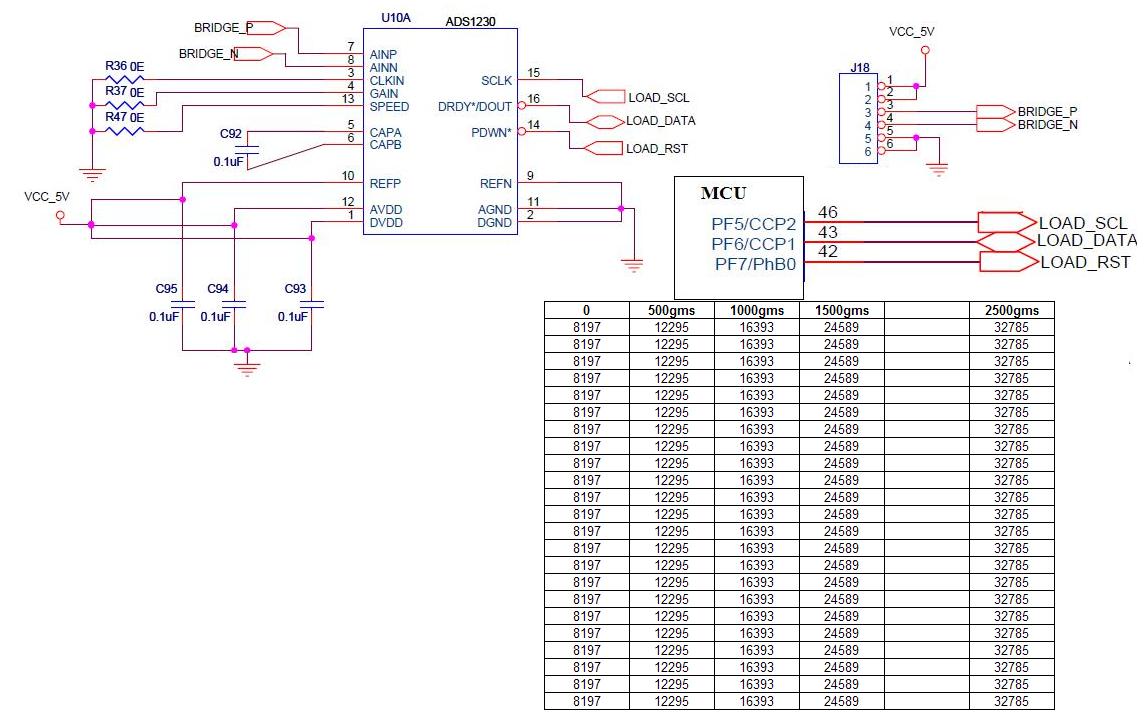
I want to use ADS1230 for the weighing scale application.I am using LM3748 as my MCU.The loadcell(4 wire) output is 1.9870mV/V and the excitation voltage is 5V.

My question here is the loadcell which I am using can be used with ADS1230.

Thanks And Reagards,

Shenoy

===================================================


  • Shenoy,

    At approximately 2mV/V and using 5V excitation you will get a maximum deflection of about 10mV, which is within the range of the ADS1230.  You will want to use the highest PGA setting to get the best resolution for your measurements.  Also, remember that the load cell will have some voltage offset that will need to be calibrated out of your readings.

    There is a reference design using the ADS1230.  It uses a MSP430, but the design can be adapted to any controller.  I would suggest reviewing the user guide for additional information.

    http://www.ti.com/lit/pdf/sbau125

    Best regards,

    Bob B

  • Dear Bob,

             Thank you for the Response.Can you please review the following design details.

    1. Circuit Settings

           - SCLK is connected to the MCU Port pin

           - DRDY/DOUT is connected to MCU port pin.(Initially configured as Interrupt pin and after getting the Interrupt,this pin is configured as Input pin to grab the data serially)

           - PDWN is connected to port pin and Toggled On Power ON and Kept High permanently

           - CLKIN and SPEED are pulled low and GAIN is pulled to 5V

    2. Firmware Details

     - Once the Interrupt is received, the SCLK pin is toglled 24 times with a delay of 250 microseconds(CLK pin ON time = 250uS and OFF time = 250uS)

    - Data is read after 250uS of delay from the time the SCLK is made high.

    - I am able to get data, but the counts are not changing for the smaller weights.For Example If I keep 500 gms weight on the weighing plate , it gives me 16394.I am not sure whether the count received is correct or not.

    - Another observation is I am getting these readings every 2 sets of reading.My receive Buffer Shows :

    0x00 0x42 0x46

    0x01 0xff 0xff

    0x00 0x42 0x46

    0x01 0xff 0xff

    This keeps repeating.


    Can you please suggest what could be wrong .

    Please note that I have verified the laodcell linearity with the Interface provided by the manufacturer.


    Thanks And Regards,

    Shenoy

    ================


  • Shenoy,

    Do you have the capability of taking scope screen shots, so we can actually see the data?  A couple of other questions, what is the PGA setting and VREF values used?  What is the range of your load cell?  What is a no load (no weight on it) reading?  From this we should be able to get an idea of what the reading should be for comparison.  Also, would it be possible to send me a schematic, or a portion of the schematic that entails the load cell connections to the ADS1230?

    Thanks,

    Bob B

  • Dear Bob,

            Thank you for the response.

    Please find the attached file which gives the ADS1230 connections with MCU.Also I have pasted few reading which I got during testing.

    Below are the data on the Loadcell:

    Capacity: 100 KG

    Output : 1.9780mV/V

    Input Impedance: 400 +/- 30 Ohms

    Output Impedance: 350 +/- 30 Ohms

    Thanks ANd Regards,

    Shenoy

    ===========================


  • Shenoy,

    I am confused about a couple of things. In an earlier post you said the GAIN input is high, but the schematic shows that it is pulled low. You also state that the load cell is rated for 100 Kg, did you mean 10 Kg? The data seems to come a lot closer to to 10 Kg. The data that you show, is it really that stable? I would suspect it to move around from reading to reading. Also in an earlier post you said you had alternating readings. Were you able to track down the source of that problem?

    Let's investigate this a little further. At 1.978 mV/V at 5V excitation, there is a maximum deflection of 9.89 mV. I am going to assume that the load cell is actually rated at 10 Kg, so that would compute to 989 uV per gram. At a gain of 64, one lsb would be 75 nV. Putting this all together excluding noisr, gain and offset error, 500 grams would produce a code of 6,593. 10 Kg would produce a code of 131,860. I find this number interesting as it is approximately 0x1FFFF, which is one of the alternating values you had mentioned previously.

    There will be an offset, do you run the offset calibration? If not, I would suggest that you run the calibration and retake the readings. Are the weights you are using calibrated weights? That is also important when verifying your system. Another thing to consider is the stability of your voltage source. This should be a clean supply. It may also help to use a larger cap at the reference pin. A 4.7-10uF cap can be used and should be placed as close as possible to th REFP pin.

    Looking at your data and subtracting out the offset at 0 V, the codes are about 2/3 the value they should be for 500 g to 1 Kg, but are double from 500 to 1K which would be correct. However, the more interesting pattern is that each reading changes by a factor of two for 500 to 1.5 Kg. That would be totally wrong. So I wonder a little about your code, and how you determine the values. Have you verified your data on an o-scope to make sure that your calculated reading from the micro is the same as the data reading displayed on the scope?

    Please verify to me the data via o-scope, the actual gain settings, stability of the readings and load cell maximum load.

    Thanks,

    Bob B

  • Dear Bob,
     
       Thank you for the response.Please find the further details for your review. (My Responses/ answers are in BLUE

    Regards,

    Shenoy

    -------------------------------------------------------

    Answers for your Query :

    I am confused about a couple of things. In an earlier post you said the GAIN input is high, but the schematic shows that it is pulled low.

    Sory for the confusion,Actually I started with GAIN input as in the schemtic(low).Then I wanted the check with Gain with 128 I pulled the GAIN pin to HIGH.(Just to mak FSR lesser).This gave me the similar readings by dobling the values.


    You also state that the load cell is rated for 100 Kg, did you mean 10 Kg? The data seems to come a lot closer to to 10 Kg.

    The load cell is of 100KGs.I also have a calibration Report for the same from the vendor.

     The data that you show, is it really that stable? I would suspect it to move around from reading to reading. Also in an earlier post you said you had alternating readings. Were you able to track down the source of that problem?

    The readings are very stable!!Which made me very confusing.(This is the reason the weight of one gram is not recognised) As I mentioned in my previous post abt the alternating readings,please find the readings as below.I am taking  2nd set of the reading as my correct wait.( I am storing the values in a buffer and checking the buffer in debug mode.These values are for No weight kept and with GAIN PIN Pulled HIGH).

    0x01 0xff 0xff 0x00 0x40 0x09 0x01 0xff 0xff 0x00 0x40 0x09 0x01 0xff 0xff 0x00 0x40 0x09 0x01 0xff 0xff 0x00 0x40 0x09       ( for 0 gm)

    0x01 0xff 0xff 0x00 0x60 0x0D 0x01 0xff 0xff 0x00 0x60 0x0D 0x01 0xff 0xff 0x00 0x60 0x0D 0x01 0xff 0xff 0x00 0x60 0x0D     ( for 500gms) 

    Let's investigate this a little further. At 1.978 mV/V at 5V excitation, there is a maximum deflection of 9.89 mV. I am going to assume that the load cell is actually rated at 10 Kg, so that would compute to 989 uV per gram. At a gain of 64, one lsb would be 75 nV. Putting this all together excluding noisr, gain and offset error, 500 grams would produce a code of 6,593. 10 Kg would produce a code of 131,860. I find this number interesting as it is approximately 0x1FFFF, which is one of the alternating values you had mentioned previously.

    There will be an offset, do you run the offset calibration? If not, I would suggest that you run the calibration and retake the readings.

    I have run the offset callibration process.

    Are the weights you are using calibrated weights? That is also important when verifying your system.

    I am not using the Calibrated weights.But I have an standard weighing scale,In which I am measuring the weight and testing with the our system

    Another thing to consider is the stability of your voltage source. This should be a clean supply. It may also help to use a larger cap at the reference pin. A 4.7-10uF cap can be used and should be placed as close as possible to th REFP pin.

    The voltage source is from the USB port of the LAPTOP.I will try this by using 10uF cap at REF pin.

    Looking at your data and subtracting out the offset at 0 V, the codes are about 2/3 the value they should be for 500 g to 1 Kg, but are double from 500 to 1K which would be correct. However, the more interesting pattern is that each reading changes by a factor of two for 500 to 1.5 Kg. That would be totally wrong.

     So I wonder a little about your code, and how you determine the values. Have you verified your data on an o-scope to make sure that your calculated reading from the micro is the same as the data reading displayed on the scope?

    Please find the code for getting the data from the ADS1230.GET DATA function is called on each interrupt from the ADS1230.Calibrate function is called during PowerON.

    void


    Get_DATA(void)

    {


    unsigned int Bit_cnt=0;


    unsigned long

    ulClockMS;

    Config_ADS1230_DATA_PIN();


    // Get the value to pass to SysCtlDelay() in order to delay for 1 ms.

    ulClockMS = ROM_SysCtlClockGet() / (3 * 250);


    for

    (Bit_cnt=0;Bit_cnt<8;Bit_cnt++) //Bit 19,18,17,16

    {

    GPIOPinWrite(GPIO_PORTF_BASE, GPIO_PIN_5,GPIO_PIN_5);

    //clock = high;

    SysCtlDelay(ulClockMS * 1);

    tmp_G = GPIOPinRead(GPIO_PORTF_BASE, GPIO_PIN_6);

    tmp_G &= GPIO_PIN_6;

    tmp_data = 0;

    Convert_Data((7-Bit_cnt),tmp_G);       // pack the data bit into byte format

    Weight_Reading[Weight_ctr] = tmp_data;

    GPIOPinWrite(GPIO_PORTF_BASE, GPIO_PIN_5,0);

    // scl = low

    SysCtlDelay(ulClockMS * 1);

    }

    // end of for(Bit_cnt=0;Bit_cnt<4;Bit_cnt++)

    Weight_ctr++;


    for(Bit_cnt=0;Bit_cnt<8;Bit_cnt++) //Bit 15,14,13,12,11,10,9,8

    {

    GPIOPinWrite(GPIO_PORTF_BASE, GPIO_PIN_5,GPIO_PIN_5); 

    //clock = high;

    SysCtlDelay(ulClockMS * 1);

    tmp_G = GPIOPinRead(GPIO_PORTF_BASE, GPIO_PIN_6);

    tmp_G &= GPIO_PIN_6;

    Convert_Data((7-Bit_cnt),tmp_G);        // pack the data bit into byte format

    Weight_Reading[Weight_ctr] = tmp_data;

    GPIOPinWrite(GPIO_PORTF_BASE, GPIO_PIN_5,0);

    // scl = low

    SysCtlDelay(ulClockMS * 1);

    }

    // end of for(Bit_cnt=0;Bit_cnt<8;Bit_cnt++)

    Weight_ctr++;


    for(Bit_cnt=0;Bit_cnt<8;Bit_cnt++) //Bit 7,6,5,4,3,2,1,0

    {

    GPIOPinWrite(GPIO_PORTF_BASE, GPIO_PIN_5,GPIO_PIN_5);


    //clock = high;

    SysCtlDelay(ulClockMS * 1);

    tmp_G = GPIOPinRead(GPIO_PORTF_BASE, GPIO_PIN_6);

    tmp_G &= GPIO_PIN_6;

    Convert_Data((7-Bit_cnt),tmp_G);         // pack the data bit into byte format

    Weight_Reading[Weight_ctr] = tmp_data;

    GPIOPinWrite(GPIO_PORTF_BASE, GPIO_PIN_5,0);

    // scl = low

    SysCtlDelay(ulClockMS * 1);

    }

    // end of for(Bit_cnt=0;Bit_cnt<8;Bit_cnt++)

    Weight_ctr++;

    Config_ADS1230_INT_PIN();             

    }


    void


    Calibrate(void)

    {


    unsigned long ulClockMS;


    unsigned char ctr = 0;

    Config_ADS1230_DATA_PIN();


    ulClockMS = ROM_SysCtlClockGet() / (3 * 250);


    for(ctr=0;ctr<26;ctr++)

    {

    GPIOPinWrite(GPIO_PORTF_BASE, GPIO_PIN_5,GPIO_PIN_5); 

    //clock = high;

    SysCtlDelay(ulClockMS * 1);

    tmp_G = GPIOPinRead(GPIO_PORTF_BASE, GPIO_PIN_6);

    tmp_G &= GPIO_PIN_6;

    tmp_data = 0;

    GPIOPinWrite(GPIO_PORTF_BASE, GPIO_PIN_5,0); 

    // scl = low

    SysCtlDelay(ulClockMS * 1);

    // end of for()

    GPIOPinWrite(GPIO_PORTF_BASE, GPIO_PIN_5,0); 

    // scl = low

    SysCtlDelay(ulClockMS * 412); 

    // wait for 103 mS

    }


  • Shenoy,

    I think we have a couple of things going on.  Regarding the alternating readings, it could be that because you are reading in debug mode, the actual data is not getting read ever 100 ms.  The second issue is with the 100KG load cell, you are trying to read weights that are acutally in the noise region.  The ADS1230 has effective bit resoultion of 17.5 bits.  See page 20 of the datasheet for a more detailed description of what is happening.

    You really need to look at the data/clk and read the data coming from an o-scope.  You can also verify my assumtion that the data is not being read quickly enough in the debug mode.  Also, you should see the lower bits moving around.

    What I can tell from your code is that you are clocking in the data correctly, but I'm not sure if the debug mode is handling your buffers correctly.  Verifying the scope data with the debug data should be done.  If at all possible, post the scope plots.

    Best regards,

    Bob B