This thread has been locked.

If you have a related question, please click the "Ask a related question" button in the top right corner. The newly created question will be automatically linked to this question.

ADS1281: ADS1281 low frequency low level tones - other than idle tones

Part Number: ADS1281

We are using the ADS1281 in one of our designs at CERN to measure the current on the magnets of the accelerator. It's a low frequency, high resolution, high precision measurement and we need performance at the part per million level.

When testing some of our ADS1281 boards, we have observed very low level, low frequency periodic tones which do not exhibit the linear frequency-voltage characteristic of Sigma-Delta idle tones. The frequencies of the tones are slightly different between different ADCs (≈1 Hz), but the amplitudes differ by up to 15 dB in the investigated units. In some they don’t pose a problem, in others it’s at the limit of what could be problematic for us. The amplitude is quite small, in the worst case we saw a tone of about 6.5 uV pkpk at a frequency around 10Hz.

 These tones seem to come from the ADC and not from the signal conditioning circuit or the input signal: the analogue input of the ADC was studied carefully with a high-gain, low-noise differential amplifier. No signals resembling the tones were seen. A common coupling mechanism, e.g. through the supply lines, voltage reference, or common-mode bias voltage, can be ruled out because we have three ADS1281 channels in the same board and in different cases some of them don’t show the tones while others do, at different levels.

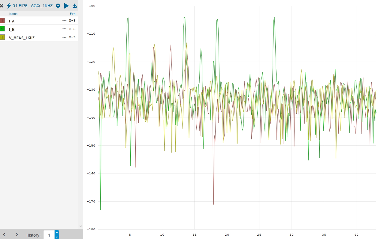
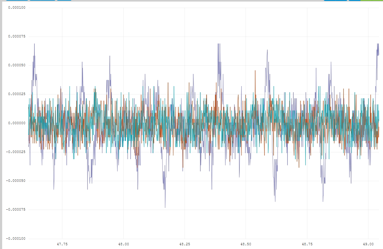
To evaluate the problem, which we saw after filtering, we obtained the bitstream from M0 and M1 for 1 unit to see if the problem can be seen in the bitstream. The results are below for two different ADS1281 channels.


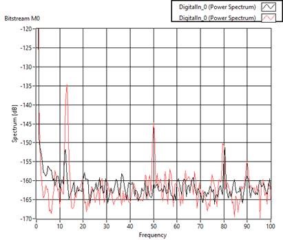
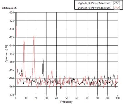
I also show below the M0 and M1 full-bandwidth spectra for two devices – please notice the “bad” device that has the high tones also has somehow different distribution of the regular idle tones. More of them appear in the M1 stream. Also, the sidebands around the idle tones seen in the M0 stream are different. One of the hypothesis we discussed was that could be related to the dither. A colleague suggested perhaps it’s the spread of the amplitude or frequency of the internal dither generator or some kind of beating with other frequency? Or an aliased version of that.


We would be grateful if someone could help us with some hints. For the moment we are replacing the ADCs that show this tones at a non-acceptable level for us. We consider that below 1.5uV pk pk the problem is negligible for us.

  • Hi Miguel,

    Welcome to the TI E2E forums!

    For the above tests, what was your input signal? Did you short the inputs or apply some external source?

    You mentioned that the tone did not have the normal linear frequency vs input voltage relationship, in what way did you vary the input signal and what was the behavior of the tone? Did it go away with larger input signals?

    Also, if you could share a schematic of your circuit that would be very helpful to me! Please email it to "pa_deltasigma_apps@ti.com" if you prefer not to post it to the forum.

    Thanks,
    Chris
  • Dear Chris,

    Thank you for your reply.

    The input signal was generated using a WAVETEK 4808 voltage calibrator. Please notice that, to ensure there were no such tones on the input signal, the analog input of the ADC was studied carefully with a high-gain, low-noise differential amplifier. No signals resembling the tones were seen.

    With the WAVETEK 4808, we varied the input signal around zero, in steps of a few milivolt, and then tens of milivolt and finally volts. We could see the expected ADS1281 idle tones, which rapidly moved out of the baseband. However the low frequency tones we mentioned in my post, did not respond in the same way. They stayed relatively stable in their positions, just slightly changing their frequencies and in a non linear fashion. As you can see in my post, we tested at 10V input and these low frequency tones are still there.

    Again, please notice that they are only visible in some units. The percentage of units were we were able to detect this is very small. However it seems to us they are also there in other units but just that they are much smaller and difficult to see if you are not looking for them.

    I will send the schematic to the email you sent me.

    Regards,

    Miguel Bastos
  • Dear Chris,

    I already replied to your comment, but I don't see it in the forum so I am replying again.

    First of all thanks for your help.

    The input was generated with a WAVETEK 4808 voltage calibrator. To be sure the tones were not present in the input signal, the analog input of the ADC was studied carefully with a high-gain, low-noise differential amplifier. No signals resembling the tones were seen.

    with the WAVETEK 4808 we varied the input voltage of a few milivolt around zero. Then we adjusted it of a few tens of milivolt and finally some volts. We could see the expected ADS1281 voltage dependent, frequency moving idle tones. they quickly moved out of the baseband as we adjusted tens of mV. However we could also see the described low frequency tones that showed none or little dependency with he input voltage and stayed always around the same frequency even at 10V. Frequency varied but just slightly and in a non linear fashion.

    I am sending the schematic to the indicated address.

    Regards,

    Miguel Bastos
  • New information on this issue: I replaced the ADC chip (ADS1281) in one of the board where these tones were too big and after replacement the amplitude of the tone decreased of about 20dB. So the tone seems to come from the ADC chip.
  • Hi Miguel,

    Thanks for your patience and sorry for the delayed response!

    I'm afraid I'm a bit confused by your results when looking at the M0 and M1 modulator output stream separately. Typically, you would want to combine these modulator streams (using equation 1 in the ADS1281 datasheet) to get the final low-noise modulator result. From the combined bit-stream outputs, you could look at the spectrum to see the actual ADC performance. What I'm getting at is that it may be possible to see a tone in the each of these bit-streams separately, but when subtracting M1 from M0 and looking at the combined result you might see this tone go away. Have you tried looking at the combined bit-stream spectrum?

    Regarding the tone being an artifact of the device, would you be able to try putting a couple of known "bad" parts onto known "good" boards to see if the problem is truly following the parts?

    Best regards,
    Chris
  • Hi Chris,

    The idea of showing separately M0, M1 was to help understanding where the tones could be coming from, within the ADC chip, if indeed they were coming from there. Obviously the problem was first detected on the combined and filtered bit stream output and it was only when we started investigating and reached the conclusion this could be coming from within the ADC that we decided to look at M0 and M1 separately.

    Below I show the spectrum of the combined and filtered bit stream, as we use it in our application. Please notice that this is not the same unit as from my original post, as that unit was not available today. So I used another unit where these tones are also visible. The FFT below shows two ADC channels. One is clearly worst (>10dB difference)

    For information, we have more than 1000 boards installed in the field with this ADC, in operation for half a year now. We have detected this problem only in a small number of them, and it's not really a problem for operation for now. As I said, we suspect these tones are present in all units and they are just too small to be seen.

    One more note: is a small correction to be done in one of the graphs in my original post: the very last graph, with the full spectrum, refers to M1 and not M0 as it's marked on the top left of the graph.

    thanks again for looking into this,

    Miguel

  • The graph in the previous post was obtained with the inputs short circuited to ground.
  • I would like to add that we are not using the internal digital filters of the ADS1281. We are using our own digital filter. That is also why we wanted to send you the original bit stream showing that the tones are there before the digital filter.
  • Hi Miguel,

    Ok, I just wanted to be sure that the idle tone was present in the combined filter response.

    Do you have any other clocks or switching power supplies in your system that might have a frequency close to the ADC's modulator clock frequency (fclk/4)? Signals around mod clock frequency could alias back into the passband.

    Does the issue persist even after resetting the ADC or power cycling the system?

    Have you seen any cases where moving a "bad" part on to a known good board has resulted in the the problem following the part? I'm not aware of any cases of similar device behavior; therefore, this sort of test might help determine if this is a system- or device-level issue. If everything points to a device-level issue then we might want to consider returning some of the bad devices to run them through our tests again.

    Best regards,
    Chris

  • No clocks or switching power supplies swicthing at frequencies close to the ADS1281's, but I will investigate a bit further the possibility of a multiple frequency being present.

    Yes, the issue persists when we powered cycle the system.

    I will mount a "bad" part on a "good" board to see if the problem follows the part.

    I will come back to this subject only in a couple of weeks as I will be busy with another project.
  • Hi Miguel,

    OK, thanks for the update! Let us know what you find when you get the chance and we'll continue supporting it from there.

    Best regards,
    Chris
  • Hello,

    As promised, I am back to this subject after mounting a ADS1281 chip considered to have the unusually high amplitude low frequency tone on a channel that had another ADS1281 that didn't show the issue. We verify that the problem follows the ADC chip.  

    In the first image of the FFT the worst channel is shown in yellow(ish) and identified as Vmeas. We see low frequency tones at around 10 and 15Hz. The other channels IA and IB show tones but with more than 10dB less amplitude.

    The second image shows the result after swapping the ADCs between the bad channel (Vmeas) and one of the others (Ib). In the picture the worst behaviour is now corresponding to the green curve (Ib). So the tones follow the chip.

    It is interesting to observe though that the frequencies of these tones are not repeatable. They seem to move from one test to the other. They are probably aliased versions of some other frequency or a "beating".

    Again, any help would be welcome. We can send you the chip if you want.

    Regards,

    Miguel

  • Hi Miguel,

    I think at this point I'll need to have a couple of the poor performing parts returned so that we can take a look at them.
    We can run them through final test again to see if they pass or fail our functional and performance tests. Once we've gathered that info, from there we can try to see if we can duplicate the issue on the bench.

    For bench testing, we'll just need to coordinate to be sure that we are testing the device under similar conditions as you.


    Can I contact you directly, using the email address provided in your myTI account, with additional instructions for returning devices?


    Thanks and best regards,
    Chris

  • sure, please contact me through that address,