This thread has been locked.

If you have a related question, please click the "Ask a related question" button in the top right corner. The newly created question will be automatically linked to this question.

LM98725: Dead frames using the LM98725

Part Number: LM98725

Hello everyone,

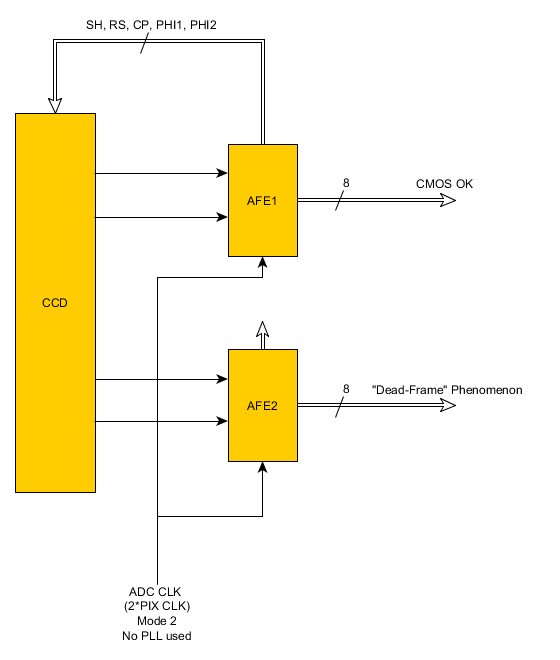
we have a CCD sensor that outputs 4 analog signals, which are connected to 2 LM98725s (to 2 channels in each AFE), that output the data in the CMOS output format from the DOUT pins. 

Both of the AFEs get the same INCLK (runs at ADC clock, i.e. 2x CCD clock) and SH_R, they get the same control register values and both generate the same control signals, but just the first one's control signal pins are connected to the CCD sensor (the second AFE's control output pins are unconnected). The AFEs use CDS sampling mode. Only the high-byte of each CMOS output is used (i.e. producing 8bit pixel values).

Most of the time the data that we get from all 16 DOUT pins is correct, but sometimes in the second AFE we get dead frames. In this faulty state, the AFE randomly creates dead frames, where the CMOS outputs give zeros (0x00) for the whole frame.
This faulty state happens just in 2% of the cases after reset and init of the entire device, and then it remains failing randomly until the next reset.
In the remaining 98% of the cases after reset and init of the device, everything works consistently and correct.
The only way to recover from the faulty state without resetting the whole device is by resetting the state machines AND the registers of the AFE (via register command), and then sending the same register values that it had in the faulty state (resetting only the state machine does not help).
However, all the control signals are correct (even though they are not used), and if we read all the registers and compare them with the first AFE (which works correctly), all of them match (except individual PGA and ADAC offset values).

This consistently happens only to AFE #2, but never to #1, also in other prototypes of the same hardware.
Both AFEs are essentially connected in the same way, however, only the control signals of AFE #1 are forwarded (both for the CCD sensor and for the camera interface), and AFE #2 is only sampling the signals based on the same input clock.
Note that if fixed AFE CMOS output test values are selected (via register settings), the correct values appear in the digital outputs also in the faulty state.

Concluding from that, it appears as if all function blocks within AFE #2 work (SH and high speed signal generation, input sampling), but the AD conversion has some sort of random problem, resulting in randomly created "dead" frames of value "0x00" for the entire sensor frame...
I'd like to know if you have ever seen such effect with the LM98725, and if the fact that the control signals are not connected in the AFE #2 could have any negative influence in it.

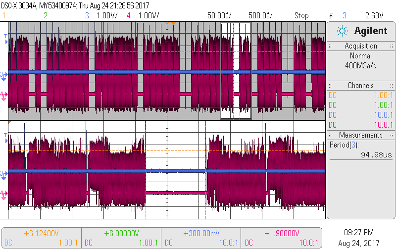
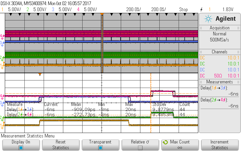
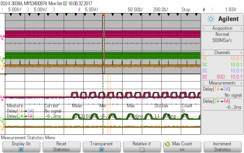
The attached figure shows the SH_R signal (in blue) sending a pulse every 95us and the DOUT6 (pink), where the dead frames can be appreciated every now and then.

Thanks in advance.

Best regards,
Inaki Lujambio

  • Hello Inaki,

    Thanks for your question. I will contact the applications engineer in charge of this device.
  • Hello,

    Apologize for late reply, I'm investigating your conditions and I'll let you know soon my recommendations.

    Regards,

    Costin  

  • Hello Inaki,

    If I understand correctly, you experience this issue in 2% of your systems. For 2% of your systems, the issue does not go away after hardware reset, but it will go away after a software reset and reloading the registers, correct?

    When you experience the faulty state, can you read the registers back? Do the values you read back match the values you wrote? If any values change, then that might hint at where the problem occurs.

    Can you do a few ABA swaps to help determine if the issue follows the board, the device, or the location? First, on a board that exhibits this issue, can you swap the two chips with each other and retest? Does the issue follow the chip or the location? Second, can you swap the IC in the failing location to a board that is known to work? Also, please put the known working IC on the failing board to help correlate.
  • Hello Inaki,

    Seems to me a timing issue.
    If I understood correctly, AFE1 controls both CCD. It is possible to swap the AFE? I'm expecting to get same results the new number 2 AFE to have dead frames. The second AFE does not provide the control signals to CCD number2, it will not properly adjust internally the sampling signals

    Thank you,
    Costin
  • Hi James,

    All 10 prototype systems that we tested get into the "dead-frames" fail-state in approximately 2% of the device-boot cases, i.e. if we restart any of the devices 100 times, we will have the fail-state on average 2 times, no matter which system we use. Once in this state, approximately 10-20% of all the produced frames are dead in seemingly random order (see oscilloscope figure in the first post), whereas the rest are correct, but this happens only in the AFE #2.

    If I read the registers in the faulty state, the only registers that are different in the faulty AFE (AFE #2) are the ones related to the PGA gain and analog and digital offset, and the differences are small. The same registers are also different in the AFE #1 (which works fine). If I re-send the values that the AFE #2 had in the working state, the problem persists (unless I reset the state machines and registers).

    Once in the faulty state, the only ways to get back to the working state are either resetting the whole system (power OFF/ON) or the AFE software reset of state machines and registers.

    Thank you.
    Best regards,

    Iñaki Lujambio

  • Hello Costin,

    We tested all 10 prototype devices, and all of them behaved the same way, so if we would swap the AFEs as you suggest, we would quite certainly also get the same faulty states in the new AFE #2.
    In other words this is strong evidence that it is not a fault of an individual AFE chip, but rather a systematical issue of some yet unknown nature.

    Exactly, the second AFE does not provide the control signals to the CCD, it is only used for sampling and AD-conversion.
    However, since both AFEs get exactly the same ADC clock from an external source (no PLL to minimise timing issues), and if we also assume some individual (but constant, a few ns) AFE component timing differences regarding the ADC exists, this can be compensated with the sampling fine-tuning settings (clamp-time and sample-time).
    Firstly, such an issue should not result in ~10-20% dead frames, but in 100% of the frames having bad shape (due to bad timing, its either bad or good but has no jitter).
    And additionally, we tried to adjust the sampling timing by modifying the fine tuning, but with no effect on the dead-frames whatsoever (of course the good frames changed and shifted according to the new sample timing settings).

    The figure below shows the block diagram of our system:

    Thank you.
    Best regards,

    Iñaki Lujambio

  • Hello Inaki,

    Agree with all your comments but I'm still suspecting a timing issue.
    It is possible to probe AFE's clock input, control signal and do a jitter comparison?
    As you mentioned since it is only 2%, that's not a delay issue.

    Regards,
    Costin
  • Hi Costin,

    After taking a deeper look at the control signals from both AFEs, we came to the conclusion that the problem is not coming from the AFE #2 in the 2% of the cases, but from each of the AFEs in 1% of the cases. It just looked like it is only AFE #2 which is faulty (and falsely suggesting something is perhaps special about its different electronic environment), because in our setup the dead frames always appear on AFE #2.

    In other words, this seems to be a systematic issue that every AFE chip has, and which is occurring with a ~1% chance when performing a full reset (power OFF/ON or state machine + full register reset).

    The problem is that when being in the faulty state, the time between the SH request and the SH interval is not constant in all the cases anymore, and it suddenly exhibits a ~20ns delay in about 10%...20% of all of the frames (SH_R-pulses).

    We always assumed that the issue was in the AFE #2, but this is only because AFE #1 is the one which provides the control signals to the CCD module, and therefore its own sampling is always correct, no matter if it is delayed or not. The other AFE #2 signals then appear sometimes earlier (AFE #1 in faulty state) or later (AFE #2 in faulty state), which causes AFE #2 to sample at wrong times, giving rise to the "dead-frame" phenomenon on output of AFE #2.


    The following figure shows the SH (SH1 output) and RS signals of both AFE #1 and AFE #2 in the working state, where:
    - Yellow: SH of AFE #1
    - Green: RS of AFE #1
    - Blue: SH of AFE #2
    - Red: RS of AFE #2


    In this case, all SH and RS signals are perfectly and consistently aligned within 1 to 2 ns, so the sampling is therefore always correct in both AFEs, as shown here:


    In the next figure we can see the state where the AFE #1 is sometimes delayed with respect to the AFE #2 (the jitter appear to be in the AFE #2, simply because the oscilloscope's trigger is in the SH of the AFE #1),

    and consequently the sampling signals do not match:


    On the contrary, the next figure shows how the AFE #2 is sometimes delayed with respect to the AFE #1.

    Both AFEs get exactly the same SH request signal, and the outcome is that one of the AFEs, in the 1% of the cases (after system reset or AFE full software reset), generates sometimes (around 10%...20% of the SH request pulses) the SH interval around ~20 ns delayed (almost half the pixel period), leading to a wrong sampling of the CCD data.

    We also run an automated test setup with 20.000 test cycles, performing resets with signal integrity check, and exactly 2.1% had the faulty state (i.e. 1.05% for each AFE).

    So there seems to be some general and systematic situation inside the AFE chip, which in 1% of the startup cases leads then to this delay suddenly and sporadically happening until next full reset. This also suggests that there is no fix other than a "init - check - reinit - check" loop at device startup...

    What are your thoughts about this ?

    Thank you very much.
    Best regards,

    Iñaki Lujambio

  • Hello Inaki,

    Seems to me internal PLL is not stable after reset. Does the system wait 50mS before sending the soft reset?
    I'm referring to datasheet page 84 note:
    "After either starting or stopping INCLK, or after Software Reset (Register Page 0, Address
    1, [4:3]), users should wait for 50 ms to allow the internal PLL and logic to stabilize before
    resuming Serial Interface communications."
    Based on pictures SH interval is corrupted, in normal operation on the bench this issue has not been reported. The only way I think it may happened is with a non stable PLL

    Thank you,
    Costin
  • Hello Costin,
    Yes, after starting the INCLK and after software reset we have a 100 ms pause. Maybe no issue was reported in your bench test, because an individual device that supplies the control signals and the sampling to a CCD does not show any problems even when the jitter exists in the SH interval.
    Is the time gap between SH_R and SH interval start supposed to be a device constant per design? What can possibly have any influence on that time delay, besides the PLL? Could you think of any register settings which may have an influence on that?

    Thank you,
    Iñaki Lujambio
  • Hello Inaki,

    Since PLL and logic is stable ( 100mS is more than enough) and same MCLK and SH_R, I don't understand why SH and RS are not stable.
    As you mention the instability is half a clock. Can you please e-mail me the registers settings to:
    costin.cazana@ti.com

    Thank you,
    Costin
  • Hello,

    Changing the pixel clock to half the value from (from 21.6 MHz down to ~10MHz) also caused the jitter to be twice as big in time (from ~20ns --> ~40ns). That means that the jitter appears to be equal to one INCLK period (INCLK = ADCCLK = 2*PIXCLK). So, as Costin said in the previous post, half a pixel period.

    Also, we tested that the dead-frame (jitter) phenomenon can also be caused by a change-of-INCLK event (without any resets, etc.). For that we run a test series comprising of 10000 times changing PIXCLK consecutively between 21.6 MHz and ~10 MHz. Surprisingly, we found the jitter-state to appear in only ~1% of the cases (summarily on both AFEs), which were exclusively when changing to the higher 21.6 MHz clock, but never when changing to 10 MHz. The same thing happened when changing the PIXCLK between 21.6 MHz and 13.5 MHz, but when we tested that with 21.6 MHz-18 MHz changes, the jitter-state appeared on the 2% of the cases, with ~50% of the cases when changing to 18 MHz and ~50% when changing to 21.6 MHz.  Looks like the jitter appears when we use higher ccd clocks.

    Best regards,

    Iñaki Lujambio