


Hello,
i am trying to communicate (read the INTERFACE Register of the ADS1262 but i only get random values (maybe the content of Data Register).
by reading the INTERFACE Register i expect a value of 0x05h but i get toggeling radom values.
here my code:
#define INTERFACE (0x02)
ADS126xReadRegister(INTERFACE, 1, &VALUE);
void ADS126xReadRegister(int StartAddress, int NumRegs, unsigned char *pdata)
{
set_adc_CS(0);
ADS126xXferByte(0x20 + StartAddress);
ADS126xXferByte(NumRegs - 1);
for(int i=0;i<NumRegs;i++)
{
pdata[i] = ADS126xXferByte(0x00);
}
set_adc_CS(1);
}
unsigned char ADS126xXferByte(unsigned char cData)
{ _BYTE tempValAdc;
tempValAdc=SPI_SendReceiveByte(_HWDEFS_AD7190_SPI, cData);
return tempValAdc;
}
void set_adc_CS(_BYTE state)
{
if (0 == state)
{
ADS1262_SELECT0;
for (_BYTE i=0;i<8;i++){
;
}
}
else if (1 == state)
{
for (_BYTE i=0;i<8;i++){
;
}
ADS1262_SELECT1;
}
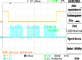
PIC 1: CS vs SCLK
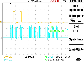
PIC 2: MOSI(DIN) VS SCLK
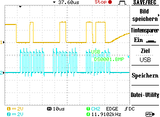
PIC 3: MISO (DOUT) VS SCLK
