This thread has been locked.

If you have a related question, please click the "Ask a related question" button in the top right corner. The newly created question will be automatically linked to this question.

ADS1258EVM-PDK: Analog input

Part Number: ADS1258EVM-PDK
Other Parts Discussed in Thread: ADS1258, INA121, INA128, ADS1278, ADS1298

Hi,

I am trying to create the ECG circuit shown here on page 9: http://www.ti.com/lit/an/sbaa160a/sbaa160a.pdf.

When I connect the analog inputs to the output from the instrument amplifier it distorts the signal. The circuit for the instrument amplifier works properly when I view the output on an oscilloscope but it becomes distorted when I add any analog output. When I try to record the data using the multiscope plugin it just looks like noise.

Are there any suggestions to fix this?

thanks,

Kaylin


  • Hi Kaylin,

    If I am understanding correctly, it sounds like you might have two different issues:

    1. The analog signal is distorted when connected to the RC + ADC load and
    2. The ADS1258 (EVM?) is not providing a valid output that matches the signal seen on the oscilloscope.

    Is that correct?

    Are you using the exact same RC circuit on the output of the INA121, as shown in Figure 8 of SBAA160?
    The output impedance of the INA121 is very similar to that of the INA128 output impedance, shown in this E2E thread:


    Are you by chance seeing oscillations or ringing on the INA's output?
    ...You'll notice that the INA's output impedance is inductive. When combined with a capacitive load this can lead to instability and ringing on the INA's output. The 1kOhm series resistor is required here to help dampen the LC resonance of the INA + RC filter.

    Also, Figure 8 in SBAA160 uses the ADS1278. The ADS1258 allows for an amplifier placed between the MUXOUT and ADCIN pins; are you connecting the INA121 before or after the ADS1258's MUX?

    Regarding the ADC's output data...

    Would it be possible for you to share your output data, some additional information on how your configuring the ADC (or EVM), and what you're your using for you input signal?


    Thanks and best regards,
    Chris

  • Yes you are correct.

    Yes I am using the same exact circuit in figure 8 of SABAA160.

    I am using a 1kHz sine wave on the ina121.

    Figure1: 1 kHz Sine wave                                         Figure 2: Output of ina121

    Figure 3: Output of ina121 when I connect it to ads1258

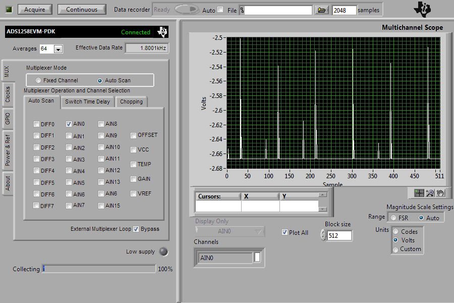
    Figure 4: Mulitscope

  • Hi Kaylin,

    The "distorted" output signal would make is seem like the ADS1258EVM is either not powered correctly or was damaged; that is not normal behavior. Also, the output of the ADS1258 shows that the ADC is over-ranged (the differential input signal is too negative). This could indicate that the input signal is not biased to the same potentail as the ADC or that the ADC is missing it's negative power supply...

    How are you connecting the INA to the ADS1258EVM?
    You must have the INA on a separate PCB or breadboard and be wiring it to the ADS1258EVM. Which pins on the EVM are you using for the input signal and how is your INA board powered with respect to the ADS1258EVM? Is there a common-ground connection between these boards to ensure proper operation?

    Are you using the ADS1258 with a unipolar supply or a bipolar supply?
    In bipolar mode, the MMB0 requires a -5 V supply connected to the "-5VA" net, in order to supply -2.5 V to AVSS.


    FYI: There is a newer device, the ADS1298, which we now generally recommend for ECG applications.


    Best regards,
    Chris

  • If it is damaged do you have any suggestions for fixing it?

    How are you connecting the INA to the ADS1258EVM?
    You must have the INA on a separate PCB or breadboard and be wiring it to the ADS1258EVM. Which pins on the EVM are you using for the input signal and how is your INA board powered with respect to the ADS1258EVM? Is there a common-ground connection between these boards to ensure proper operation?

    Answer:I have the INA on a breadboard. I am connecting the an analog pin to pin 6 of the of the INA. I have tried using all of the analog pins (A0-A15) currently I am using A0. The INA is powered using a power supply. Are you using the ADS1258 with a unipolar supply or a bipolar supply?
    In bipolar mode, the MMB0 requires a -5 V supply connected to the "-5VA" net, in order to supply -2.5 V to AVSS.. I tried using the ground from the board and from the power supply.  

    Are you using the ADS1258 with a unipolar supply or a bipolar supply?
    In bipolar mode, the MMB0 requires a -5 V supply connected to the "-5VA" net, in order to supply -2.5 V to AVSS.

    Answer: Currently I have the AC adater connected but I have tried using unipolar and bipolar. Which would you suggest?

    thanks

    Kaylin

  • Hi Kaylin,

    The only preference for use of a bipolar or unipolar supply would depend on how your input signal is biased with respect to the ADC inputs. If given the option, then a unipolar supply would be the simplest implementation since it only requires one supply.

    I would recommend that you start with measuring a known DC voltage with the ADS1258EVM to make sure that it is working and proving a valid input.

    Then you can try again with the INA, making sure the input signal's absolute voltage is between AVSS and AVDD, and the input signal's differential voltage does not exceed the reference voltage.

    Best regards,
    Chris

  • Hi,

    I connected a voltage input and I my response looked similar to the one that I got before. It seems like it is just noise.

    Kaylin

  • Hi Kaylin,

    Was the voltage measurement accurate or was it still saturating to -2.67V?

    You might want to double check the reference voltage, as the ADC result will depend on an accurate reference.
    If the reference is okay and the input signal is correctly biased to the ADC, then I might start to suspect that the EVM could have been damaged.

    Best regards,
    Chris