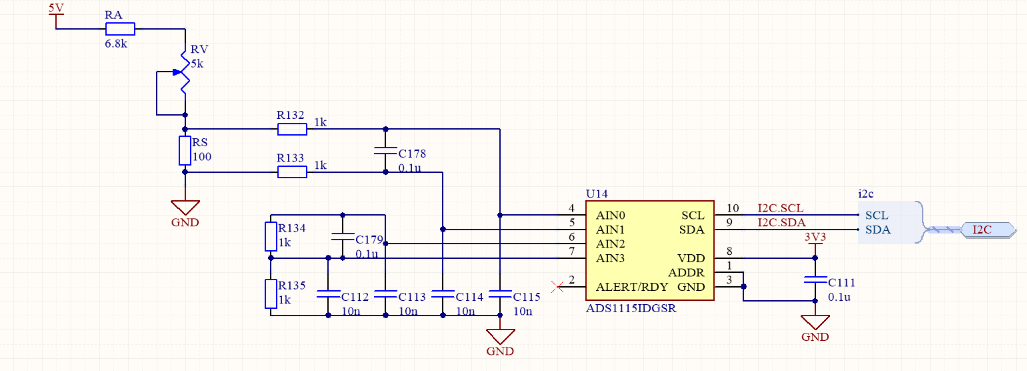
I'm using the ADS1115 to measure the voltages in two different current sense resistors. To keep dissipation low, the resistors are small, and I'm using the +/-0.256V full scale range and differential sensing.
The basic issue I am seeing is that when the differential voltage gets to +64mV (code 0x1FFF), it appears that the output codes wrap around to 0x0000. For instance, ~65mV gives me 0x009A.
I made a simplified circuit to apply small voltages to the PCB so that I wouldn't have to run larger currents through the sense resistor. The same code on the same PCB (other than the resistor change) exhibits the same behavior.
In the test circuit, I have shorted R134 across C179 to remove the second sense resistor from the circuit. By varying potentiometer RV, I can apply 40-80mV. I've also changed values so that I can get below 40mV. As mentioned above, as I increase the voltage across RS (also C178) from 0, the codes increase as expected. Once they pass about 64mV, they appear to reset to 0x0000 and begin increasing again.
- 40mV => 0x13F7 (or about 40mV when converted to volts): good
- 55mV => 0x1BDF (55mV): good
- 65mV => 0x009A (1.2mV): NOT good
- 73mV => 0x045C (8.7mV): NOT good
Looks like it is wrapping, or something is zeroing the highest 3 bits.
More details:
When I start a conversion, I use config value 0x8B03, Differential AIN0-AIN1, +/-256mV full scale, one shot mode, 8 sps, comparator off.
I wait 200 msec, then read the value. I'm looking at the raw bytes that I read, so I'm pretty sure there isn't a data conversion issue in the driver. Also, I can read back the configuration register in various configurations and get what I expect from the more significant bits. I did this because I thought, "what if something hidden in the driver is bitwise ANDing the bytes with the equivalent of 0x1FFF, thus deleting the higher bits?" I tested the single-ended AIN3 configuration that way so that bits config[14:12] would be set, and successfully read them back.
The processor is an Atmel SAMD20 using the monstrosity of the Atmel Software Framework, but there are other devices on the I2C bus that appear to be working so it is hard for me to think that something is wrong there. Plus, I do get valid readings for Vin < 64mV.
In the test circuit above AIN1 is ground; in the real circuit it is slightly above ground due to trace resistances. But the current is in a single direction, so in both circuits 0.256V > AIN0 >= AIN1 >= 0V. It appears from the device data sheet that the common mode input range can include ground, so I don't see a problem there.
The test circuit is checking a DC value. There could be some noise from the rest of the PCB, but I'm not seeing a large amount of noise. I get sample after sample of almost identical output codes.
I've tried the other valid config bits that the data sheet says will also result in +/-256mV FSR, without effect.
Although it isn't needed for my application, on the test circuit I tried reversing AIN0 and AIN1 to make the differential voltage negative. That also appears to not work correctly. -7mV gives me 0x1C00 (+56mV if converted), -62mV gives 0x0117 (+2mV), and -65mV gives me 0x1C80 (which is almost the same as the -7mV case).
More than one board has shown this issue. My colleague is going to try tomorrow with a ADS1115 prototyping board and a Raspberry Pi to see if he can replicate it that way.
I'm sure I must be missing something obvious, but I don't know what it is. The chip's configuration is pretty straightforward and seems like it would be easy to use. Any suggestions you might have would be most welcome.
Kind regards,
Rod


