This thread has been locked.

If you have a related question, please click the "Ask a related question" button in the top right corner. The newly created question will be automatically linked to this question.

Starterware/ADS5281EVM: Beginner with ADS5281EVM with TSW1405 .

Part Number: ADS5281EVM
Other Parts Discussed in Thread: ADS5281, ADS5282, ADS5400

Tool/software: Starterware

Hii..!

Anyone can please help me how to choose the clock frequency in the ADS5281EVM with HSDC pro software and I set up as per the users guide but the I can't get the capture of my input frequency. I don't even know about the firmware selection so please help me. I am starting from vary basic level for the university lab work for the medical ultrasound ADCs.

  • Hi,

    The user guide for this EVM was probably written back when the TSW1200 was the commonly available capture card, but now we support that EVM with the TSW1400.  one difference that I suspect might be hindering you is that the TSW1200 had FPGA firmware that wanted the serialized data to be most significant bit first while the ADC is default least significant bit first after reset.     So the User Guide had a step with the EVM SPI GUI that set the msb-first bit.   That is not needed with the TSW1400.    The TSW1400 was set up to work with the ADS5281 EVM just as the EVM powers up.  I was just using one of these EVMs this morning, so please see the screen capture of the ADS5282 EVM below.   all you have to do after powering on the ADS5281 EVM and connecting a clock signal, is choose the device selection in HSDCPro and enter the sample rate that matches your clock rate.  (I was using 65MHz for sample clock since it was an ADS5282.  You would use a clock frequency less than or equal to 40M I believe.)  But the following screenshot should make clear what needs to be set.  For this screenshot I did not even connect a USB cable to the ADC EVM at all, but you could if you wanted to set test patterns or other features of the ADC.

    Regards,

    Richard P.

  • ok. So I tried to install the SPI interface control software but I stuck in one of the installation procedure that show the message that no software to installed or removed and than I cant go forward and complete the installation.
  • Hi,

    What operating system are you using on your PC?  The EVM SPI GUI is pretty old, and has not been updated for Windows7 or newer.   There are steps that can be taken to make the SPI GUI work on Windows 7, but it is a bit complicated.    Please see the attached document that was created for this issue some time back.    On many of our lab PCs we have so many different SPI GUIs installed that often I can make this old SPI GUI work by right clicking on the EVM in hardware device manager and searching for an FTDI driver that is already on the PC to use, but if there are not already drivers from FTDI for the USB on the machine, then this document may be what you need.

    Regards,

    Richard P.

    2705.TI ADC SPI 5p2 installation for Windows 7 (1).docx

  • I didn't get the software cd or installation software with my ADs5281EVM so can you please send me the software ADC SPI control 5.2 which is compatible with ADs5281EVM and TSW1405 set. My email ID is hsumera@lakeheadu.ca

    I choose the clock frequancy 30MHz and the input frequency is 5MHz . So I want my output changes with I change my input frequency but I didnt get the peak at my input frequency.

  • Hi,

    several things.  you mention TSW1405 but the screenshot you have shows a TSW1400 but with no connection.   Look at the screenshot I attached previously.  Right in the middle of the bottom of the screen it says TSW1400 Board = TIWA3DHS.  That is the serial number of my TSW1400 and it is programmed into the TSW1400 at manufacture and is printed on the TSW1400.   Your TSW1400 would have a different number.  And HSDCPro should find that number and display it.  Do you have a TSW1400 in hand and is the power switch turned on?  If so and HSDCPro is not finding the serial number then you may need to open your Microsoft hardware device manager and look to see if there is a driver problem with the ports to the TSW1400.   If you have a TSW1405 and connect it, then HSDCPro should find the TSW1405 and the serial number for that and display it.     Are you using a USB port that supplies 5V power through the cable?  Some older ports are not powered.  The TSW1405 gets its power from the USB cable.   Once the HSDCPro connects to your capture card, you should be able to make a device selection like in my screenshot I selected ADS5281-82, and in the lower right corner of the window is a firmware name that has been loaded into the FPGA where it says Interface Type = ADC_1W_12b.  Without this firmware shown loaded, you won't be able to capture.

    Next, the SPI GUI that you have in the screenshot is correct for the EVM you have.  The version 5.2 was not released, but what it did have in version 5.2 is support for a different EVM the ADS5400.  That wouldn't help you any.  Version 5.1 would do.  And I think that is what is on the TI web at the moment at http://www.ti.com/tool/HSADC-SPI-UTILITY  

    But I just went to power up an ADS5281 EVM in the lab that was recently shipped from the TI estore, and it appears that in the manufacture process the assembly shop did not program the USB device.   Your EVM is probably in a similar condition, and that would explain the popup window error message that says "set bit bang'   The style of use of the USB chip is what the vendor calls their bit bang mode.  We just use the bytes down the USB cable to set the outputs of the USB chip one byte at a time and use a vector of bytes to make the SPI lines toggle the way they need to.    Again, Microsoft hardware device manager would be useful in determining if this is the issue.  If you plug in the USB to the ADS5281 EVM and under the USB connections you see something come up that says USB Serial Converter, then the USB chip on this EVM has not been programmed as it should have been in manufacture.  If that is the case, we can do one of two things.  you could return the EVM to us and we program it like it should be and we ship it back to you.  Or we can provide to you the simple utility program that is used to program the USB.   It takes I think three mouse clicks to do the programming.  if you wish to do this USB programming yourself, I have attached a zip file of the programming utility.   I changed the file name suffixes so that any virus scan software does not remove the files as potentially malicious, so the suffices would have to be changed back.   I changed .exe suffices to .eexxee, and the .dll to .ddllll, and thr .chm suffix to .cchhmm.   And in the zip folder is a .png screenshot of how to use the uutility.  you use the folder icon to select a programming template, and then the lightning bolt icon to program the EVM.    This will not fix the issue of running this old GUI on Windows7, as that is a separate issue.   This is just the programming step that should have been done on this EVM at manufacture.

    Regards,

    Richard P.

    mprog 3.0a.zip

  • Hi Richard,

    finally I got my results successfully. Thanks for you help and information.

    Now my final task is to get the real digital signal from the ADC but I don't know how to see it . Do I need any other software or I can get  it in HSDC pro software ? 

    Thanks again.

  • Hi,

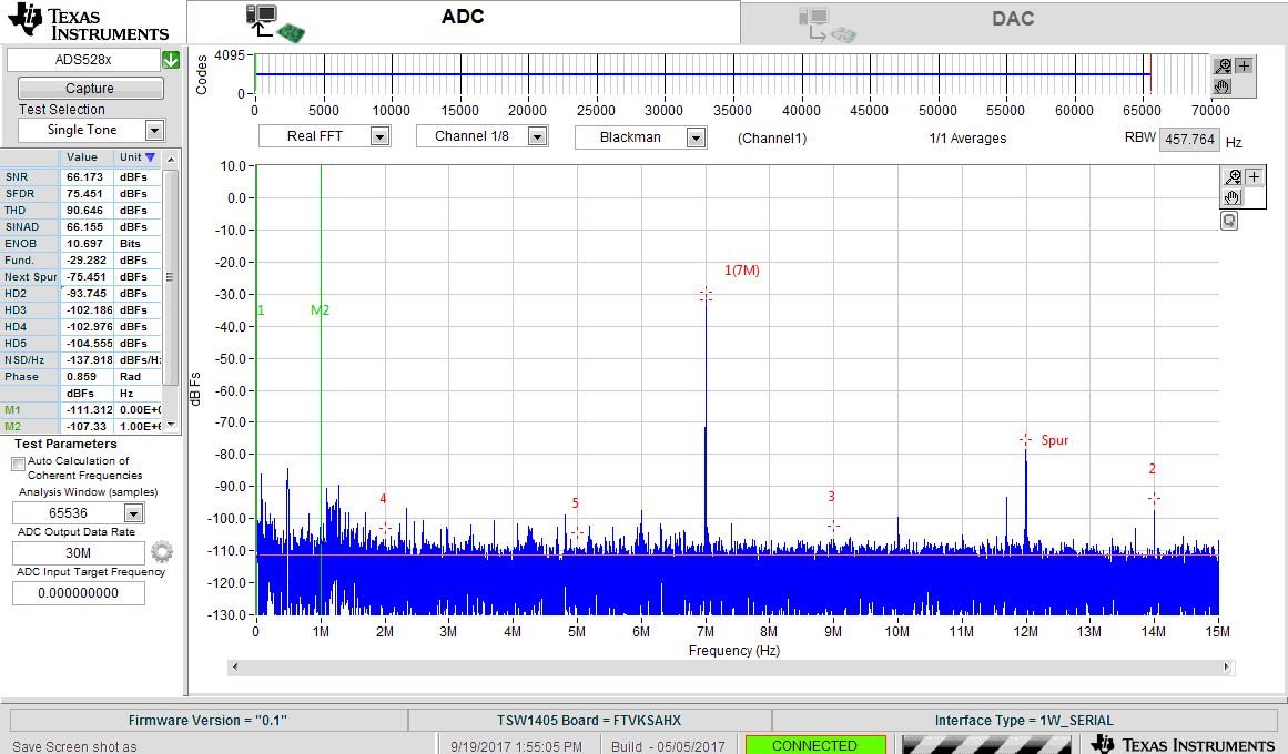
    great.  I see from the screenshot that you are connecting to the TSW1405 and getting your capture.  it looks like your input tone is around 7MHz or else is a higher tone that aliases down to about 7MHz.  Your input signal is fairly small amplitude, being about 30dB down from full scale.  you can also see that the signal is small from the top portion of the display where the sample amplitudes are plotted - the signal takes up a small range of the 12bit values of 0 through 4096 centered near mid scale, as would be expected for a small amplitude signal. 

    I'm not completely clear on what you are asking for.  if you want to get the samples themselves saved off to a file to be analyzed or processed by some other means than HSDCPro, then in the drop down menus of HSDCPro there is a menu item for 'save codes as csv file'.  This stands for comma separated value file, standard for files that can be opened with a spreadsheet or Matlab or something else.   Usually in a csv file, a comma is used to delineate numbers across on the same row, and tab or carriage return used to delineate numbers down a column.  For a multi channel capture, samples on a row are samples from the channels, while each row is the next sample.

    I am puzzled by one thing in your screenshot though.   The TSW1405 uses only what capture memory is available in the FPGA on the capture board, which is 1Mbit.  Dividing that by 16 bits for what can be saved as samples, the TSW1405 has enough memory to save 65536 samples.   If all 8 channels are captured at the same time then that is 8192 samples per channel.   It looks like you are capturing 65536 samples from only channel 1.   ah - it has been a while since I have used this setup and I seem to recall that there are options to capture 65536 samples from one channel at a time, or half that many from two channels, or half again from four channels, or half again from all 8 channels.    ok, that makes sense.

    so is it that you just wish to save the captured data?   The drop down menus will let you do that.   if you just wish to view the captured sample data then changing where it says Real FFT to bits or codes then you can look at the data in the time domain rather than the frequency domain.

    Regards,

    Richard P.