This thread has been locked.

If you have a related question, please click the "Ask a related question" button in the top right corner. The newly created question will be automatically linked to this question.

DAC8760: DAC8760 Iout 4 ~ 20mA output question

Part Number: DAC8760

Hi Team.

I have a problem using the DAC8760.

We have to use 4 to 20mA.

However, the actual measured value at 20mA setting is 19.97mA.

For us, 0.03 mA is a very large error.

Ask if it is a characteristic of the chip itself.

And ask if you can suggest a solution.

EVM KIT and the board actually produced are almost the same.

Thanks.


  • Howdy Chun,

    And thanks for the post.  Can you provide a schematic of your application, or if you wish to keep private you can send a friend request so I may send you my email address.

    That being said, I'd be curious to know the connection scheme of VOUT, +VSENSE and IOUT.  If both VOUT and IOUT are tied together, with +VSENSE connected, this may be origin of the error, which is described in page 43 of the DS:

    "When the VOUT and IOUT pins are tied together, bit 8 of the Configuration Register (DUAL OUTEN) must be set to 0. Bits 2 down to 0 of the Control Register (RANGE) control VOUT and IOUT. Special consideration must be paid to the +VSENSE pin in this case. When VOUT is disabled, the +VSENSE pin is connected to the internal amplifier input through an internal 60-kΩ resistor as shown in Figure 83. This internal node has diode clamps to REFIN and GND. Setting bit 6 of the Configuration Register (APD) forces this internal node to be tied to GND through a 10-kΩ resistor, in effect, the +VSENSE pin is tied to GND through a 70-kΩ power-down resistor."

    There are ways around this issue, which I can follow up with, but first would like to see if this is indeed the case.

    Best Regards,

    Matt

  • Hi Matthew.

    Thank you for your feedback.

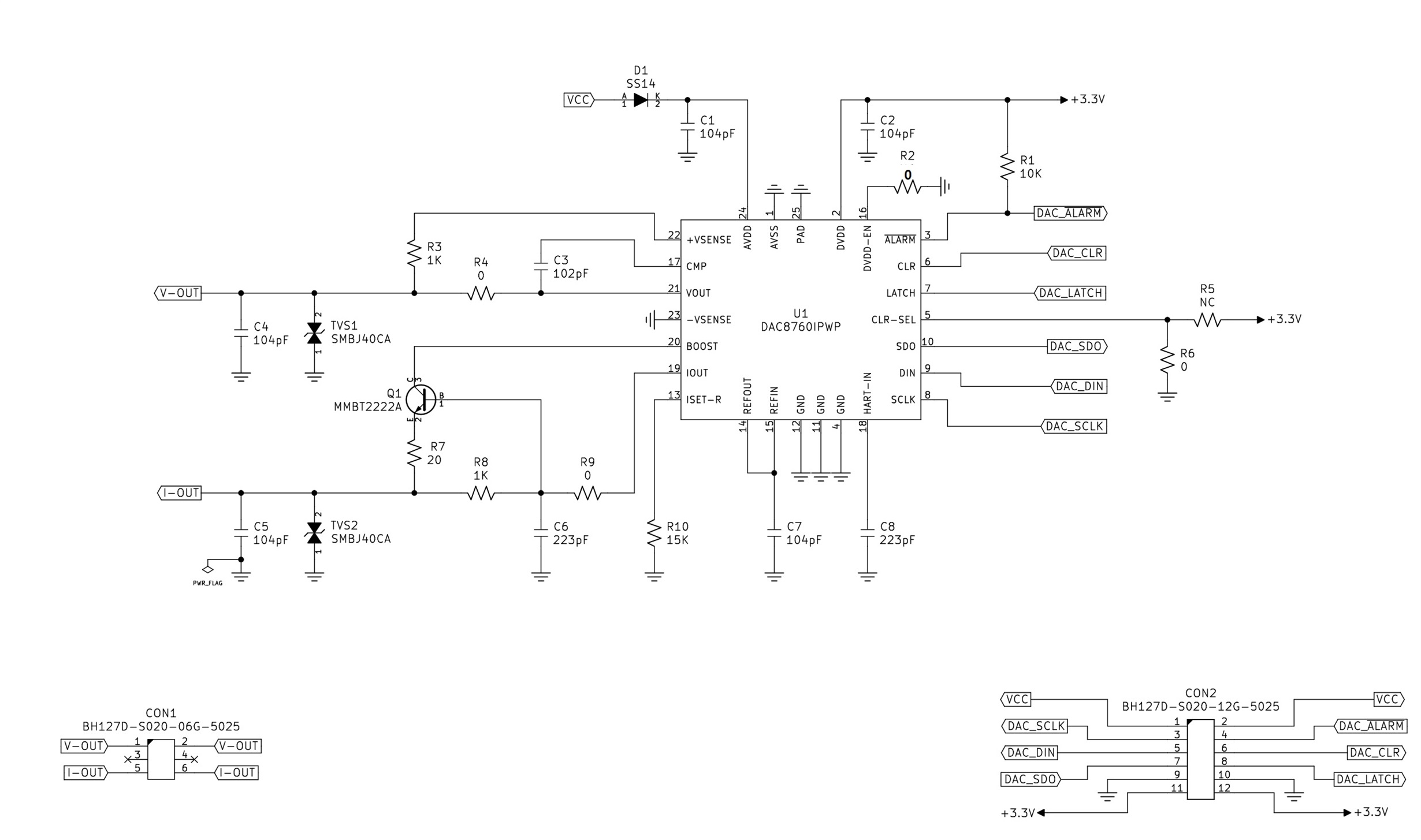
    Below is my schematic for DAC8760. Plz let me know it.

  • Hi Chun,

    It looks like you're employing the BOOST Configuration for IOUT. As indicated in page 36 of the DS, "there is some gain error introduced by this configuration as seen in Figure 47 for the 0mA to 24mA range." The error is shown in Figure 49 for the 4mA to 20mA Range, page 20. Figure 49 displays a full-scale TUE error of ~0.19%FSR for 4-20mA w/External RSET (BOOST Config). This % error correlates to what you've been measuring, as (0.0019*.016 = 0.0304mA).

    If you have any other question please let me know.

    Best Regards,
    Matt