This thread has been locked.

If you have a related question, please click the "Ask a related question" button in the top right corner. The newly created question will be automatically linked to this question.

ADS124S08: Using Analog Switch MUX509 in AFE for Thermocouple & RTD

Part Number: ADS124S08
Other Parts Discussed in Thread: MUX509

Hi Bob,

Thank you for the information! It helped us in designing the schematic.

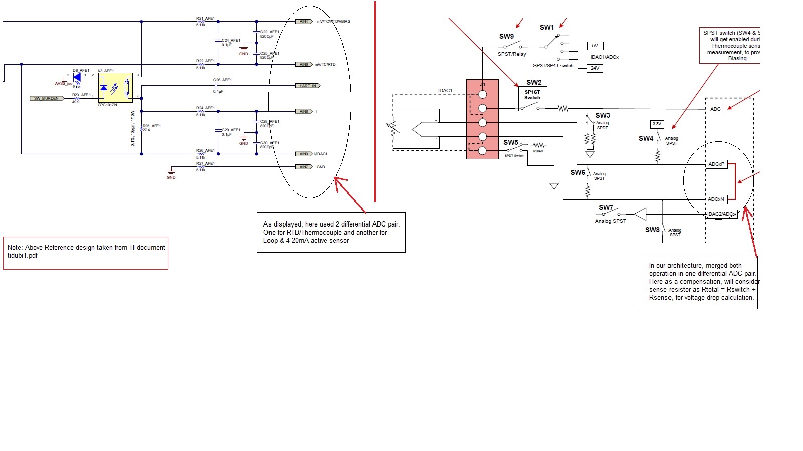
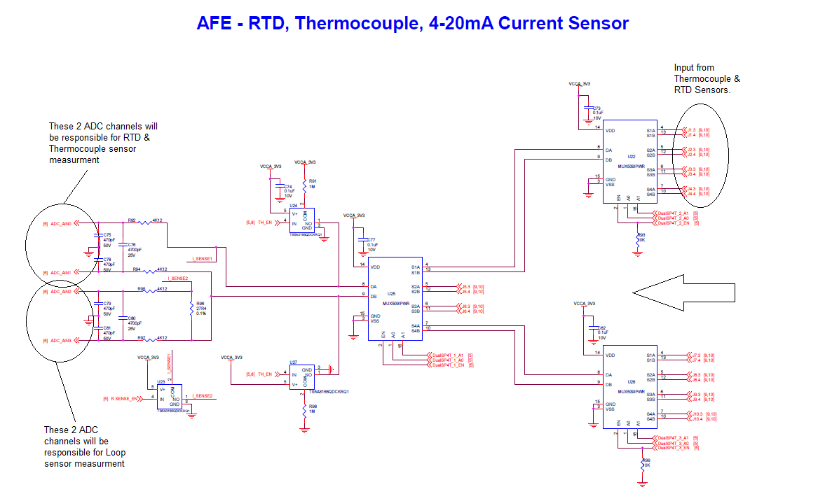
In our project we are looking to provide RTD and thermocouple sensor interface support on different 10 Connectors. For that We have used MUX509 differential analog switch in-between connector & ADC as an AFE. Also, providing external biasing using pull-up & pull-down resistors on AINP and AINN respectively.


Below added screen shot of Front End schematic for your reference:

Kindly review the same and provide your inputs on how switch will effect the measurements!

Let me know if you require more details on this.


Thanks,

Dhvanish Parekh

  • Dhvanish,


    There are two primary specifications for a multiplexer will affect measurements. First, the series impedance of the multiplexer switch may change the measurement if there is signal current running through the multiplexer. Second, the leakage from any connection to the switch may pull signal current away from the measurement.

    With series resistance, if the multiplexer is used to route matched IDAC currents into the two leads of a 3-wire RTD, the IDAC current will react with the resistance causing a voltage drop. The mux resistance from channel to channel may be large but certainly will not match, causing an error in the measurement. The resistance may depend on the temperature and the DC voltage of the signal that the mux connects.

    With leakage current, an error can occur if the leakage comes between the RTD measurement and the reference resistor. If the current running through the RTD does not match with the current running through the reference resistor, any current difference appears as a gain error. Imagine connecting an RTD with a mux and there is a 1uA leakage term between RTD and reference resistor. If the IDAC current is 1mA, then there is the equivalent of a 0.1% gain error. If the leakage is at the top of the RTD, this is not an error because the current is lost before reaching either the RTD or reference resistor. Note that the leakage usually comes from a reverse bias junction and that leakages typically are much larger at high temperatures (~85°C) than at room temperatures.

    Because of the way multiplexers are constructed, often the mux will trade off leakage for resistance. When selecting a mux, consider how it will be used, and what error it contributes to the system.

    I don't know exactly how your use of multiplexers will affect your measurement. Typically the MUX509 is low leakage, but higher in on-resistance. In this case, it depends entirely on how you route your IDAC currents for the RTD measurement. If you want, post how the currents are routed for each topology of RTD measurement that you use.


    Joseph Wu
  • Hi,


    After brainstorming on the concerns and design errors that you have mentioned related to MUX509, we came up with different analog architecture, in which we tried to minimize use of switches in-between critical measurement paths.

     I have attached PDF, having high level architecture diagram with detail description for every major block for your review.

     Below are some highlights of reformed architecture:

    1. Design requires total 26 ADC channels to provide universal ADC support on all 10x connectors. Kindly suggest combination of ADCs to support. (16-/ 12- channel ADC)
    2. Removed MUX509 mux and provided independent differential ADC channel (2x ADC) on every connector
    3. Removed dedicated differential ADC channel for Loop & 4-20mA sensor and merged it on RTD/Thermocouple differential ADC line (Attached Image1.jpg)
    4. Provided support of IDAC2 in 3-wire RTD interface for lead wire cancellation
    5. Added RBIAS resistor on GND line for RTD measurement using PGA

     Kindly review and provide your inputs.

    Analog Front End_Architecture.pdf

  • Dhvanish,


    I'm still a bit unclear on how the system is set up for each of the measurements. Part of the problem is that you don't show enough detail to figure out where the error sources are coming from. By removing the MUX509s, you remove the series resistances, but now the problem is where are the leakage terms coming from. I'd need to know what all these switches are and what the leakages are. I'm also a bit unsure about the topology of all the measurements.

    In the schematic, you have an RBIAS to ground setup, but I'm not sure where the reference resistor is (or is RBIAS your reference?). If it is a high-side reference as implied, the connection to SW6 and SW4 make a difference with their current leakage. In that topology, SW2 and SW3 might also contribute some error from leakage terms. If your reference is a low-side reference SW6 and SW7 may contribute error (and maybe SW5).

    At one point you had shown a schematic with a lot of TVS diodes connected to the system. These devices all have very large leakage terms that can contribute to the error in the measurement. Were they all removed as well?

    Regardless, I need more information about the exact setup and schematic to help debug potential problems. It would help to duplicate the "Connections of Different Sensors" section but show the reference resistors, filters, and switches. That would go a long way to reviewing the schematic.


    Joseph Wu