This thread has been locked.

If you have a related question, please click the "Ask a related question" button in the top right corner. The newly created question will be automatically linked to this question.

ADS1247: About RTD circuit

Part Number: ADS1247

Hi team,

My customer is using the ADS1247IPWR.

Please let me ask you a question.

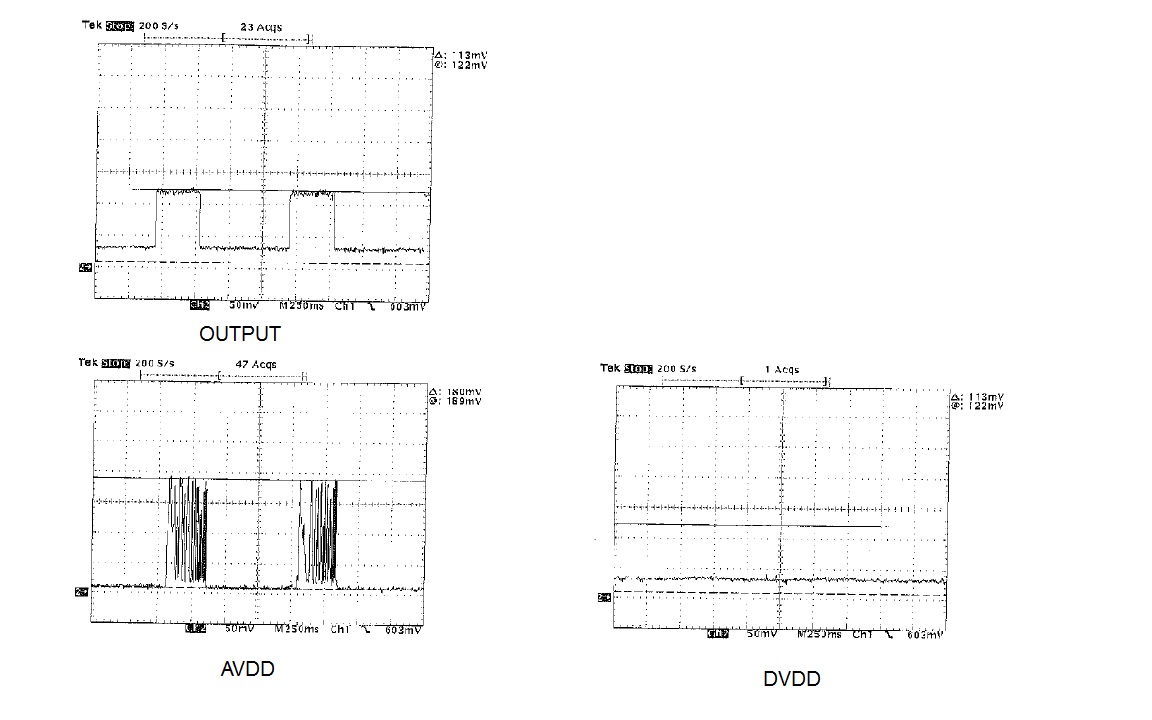
When the 3-wire RTD circuit was operated, a pulse current of about 20 mA flows to the AVDD terminal.

Is this normal?

Best Regards,

Kenji /Japan Disty

  • Kenji-san,


    I have seen cases where the AVDD current has spiked, but generally on start-up.

    With a bipolar supply, the AVDD=2.5V, AVSS=-2.5V, and DGND=0V. It seems that if AVSS starts first and gets to -2.5V, and if AVDD ramps slowly after, there may be a draw of ~15mA during the ramp. There doesn't seem to be a problem if both supplies start at the same time.

    I believe that the problem comes from the level translators used for digital communications between analog and digital sections. They may draw extra current before the supplies rise to their proper voltage. I explain this phenomenon in the following post:

    e2e.ti.com/.../2193786

    There is another case that I found where there was extra current in the ADS1247. This was caused by ferrite beads in the supply line between DVDD amd AVDD. Ferrites in the supply line often cause voltage spikes as the digital currents rush in. This thread is shown here:

    e2e.ti.com/.../2198704

    Let me know if either case is similar to your customer's circuit.


    Joseph Wu
  • Joseph-san,

    Thank you for your answer.
    There is a 0.1 μF capacitor between VREFOUT and AVSS.
    Changing the capacitor to 1uF lowers the current.
    Do you understand from this result?

    I am asking customers for electrical waveforms.

    I appreciate your support.
    Thanks and Regards,

    Kenji/Japan Disty
  • Kenji-san,


    Based on the change in capacitance, I'm not sure what the problem is. Since there is some effect from the internal reference voltage, it sounds like the problem may be related to the one described in the second post.

    Post the waveforms when you get them. In the mean time, can you please give a detailed description of the problem and what conditions and settings cause the extra current? I'll need more of a detailed description.


    Joseph Wu
  • Hi Joseph-san,

    I got the waveform.

    Below is the measured current across 10 Ω.

     · VDD, AVDD: 2.7 V

     · Using unipolar

     · Using a 0.1 μF capacitor between VREFOUT and AVSS

     · Use internal reference

     · Reference voltage is determined by input voltage of VREF1P, VREF1N

     · Excitation current 100 μA × 2

     · Data rate 20 SPS 

    I appreciate your support.

    Thanks and Regards,

    Kenji/Japan Disty.

  • Kenji-san,


    Thank you for the waveforms. As you mentioned, it looks like AVDD is repeatedly drawing about 20mA current during two 300ms periods. What is the plot labeled "OUTPUT"? Is this the measurement of some current, IDAC current, reference, or is it the output of something else?

    With the current repeatedly going high and low for AVDD, I don't know what this is. There are two things that I can think of that might behave this way. First, this could be the power supply or LDO output becoming unstable or going into some sort of current limit. Additionally, large inductances or ferrite beads on the supply may cause some spiking with the digital current. Second, this might be the internal reference becoming unstable because there AVSS return has a high impedance.

    It would be helpful to have a schematic showing the ADC and the devices supplying power to the system. Also, is the internal reference always on? or is it enabled and disabled whenever the RTD is measured?


    Joseph Wu