


Other Parts Discussed in Thread: ADS131E08
Hey Guys, how are you doing? it's a pleasure to talk with TI;
My name is Gabriel, I'm from Brazil.
I would like to know what I'm doing wrong with my project... I have been working with ADS131E08S and I don't understand the reason why I'm not receive the data correctly.
Below I will show some informations about it:
1) I'm using STM32 Microcontroller with SPI frequency 3.73Mhz;
2) My goal for now is to read CH3 and CH6 only;
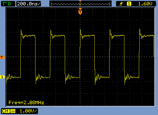
3) I'm using internall oscillator for this project, I have mesured directly by CLK pin with oscilloscope, the freq is 2,08Mhz;
4) Also I have mesured all the caps:
VREFP = 2,42V;
VCAP4 = 1,21V;
VCAP1 = 1,20V;
VCAP2 = 2,54V;
VCAP3 = 6,87V;
AVDD = 5V;
DVDD = 3,3V;
AVSS = 0V;
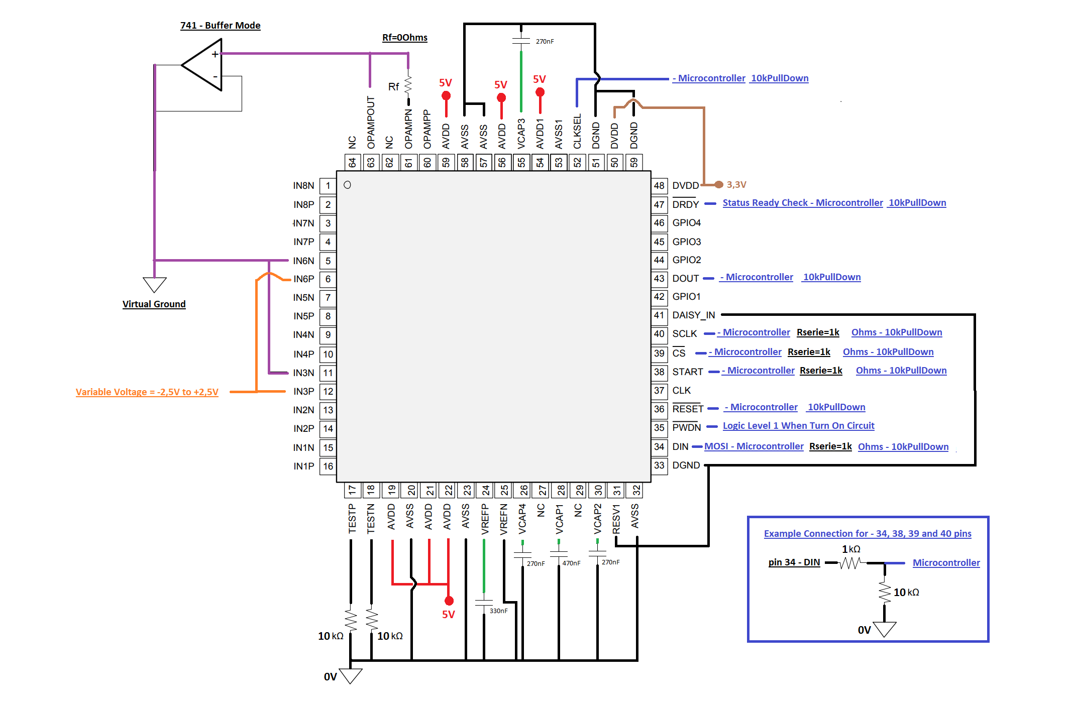
5) My schematic is attached below;
6) My main program is shown below sequentially.
- a) PWDN Pin Logic Level = 1 When turn on the power directly, START Pin Logic Level = 1 with Microcontroller;
- b) CLKSESEL Pin Logic Level = 1 with Microcontroller, delay 100us after;
- c) RESET Pin Logic Level = 1 with Microcontroller;
- Write Registers (General Code):
(0b00010001); //SDATAC
(0b01000001); //Write 12 registers starting from 01h;
(0b00001011);(0b11110100); //Register Configuration, ---- 'CONFIG1';
(0b11110110); //Register Configuration, ---- 'CONFIG2';
(0b11001100); //Register Configuration, ---- 'CONFIG3';
(0b11100000); //Register Configuration, ---- 'FAULT';
(0b10000000); //Register Configuration, ---- 'CH1SET'; //Power Down
(0b10010001); //Register Configuration, ---- 'CH2SET'; //Power Down
(0b00010000); //Register Configuration, ---- 'CH3SET'; //On
(0b10000011); //Register Configuration, ---- 'CH4SET'; //Power Down
(0b10010001); //Register Configuration, ---- 'CH5SET'; //Power Down
(0b00010000); //Register Configuration, ---- 'CH6SET'; //On
(0b10000011); //Register Configuration, ---- 'CH7SET'; //Power Down
(0b10010001); //Register Configuration, ---- 'CH8SET'; //Power DownAfter I use RDATA commands like datasheet recommended and then I receive strange bytes information:
For these tests I have apllied the same voltage for the CH3 and CH6;
Below there some tests what I did.
- Using +2,50V --> CH1= 0,0,0 - CH2=0,0,0, CH3=127,255,255 - CH4=0,0,0, - CH5=0,0,0, CN6=127,255,255 - CH7=0,0,0, -CH8=0,0,0 -- (I think the right bytes should be (255,255,255) for CH3 and CH6);
- Using +2,00V --> CH1= 0,0,0 - CH2=0,0,0, CH3=106,61,178 - CH4=0,0,0, - CH5=0,0,0, CN6=106,72,155 - CH7=0,0,0, -CH8=0,0,0.
- Using 0V --> CH1= 0,0,0 - CH2=0,0,0, CH3=255,184,62, - CH4=0,0,0, - CH5=0,0,0, CN6=255,186,7; - CH7=0,0,0, -CH8=0,0,0.
Ok, When I saw this I stoped, because I think some thing is wrong, I dont tried to apply negatives voltage untill -2,5V because this informations no make sense for me.
What I'm think is maybe I'm put some wrong register, and really I dont know why happing this, what I'm doing wrong?, thank you guys.
Regards.

