This thread has been locked.

If you have a related question, please click the "Ask a related question" button in the top right corner. The newly created question will be automatically linked to this question.

ADS5407: ADC SYNC & SYNCOUT

Part Number: ADS5407
Other Parts Discussed in Thread: DS10BR254,

In my project, i have to synchronize 64 ads5407s on 16 platforms with K7(xilinx) fpga, and now i have such problems as follow:
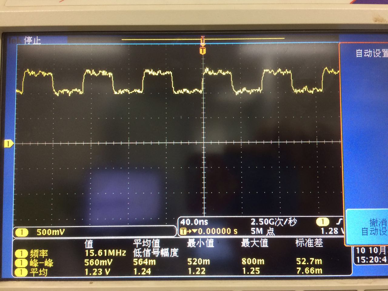
i have SYNC signal through a lvds buffer (DS10BR254) to link to ADS5407 in dc-coupled , but i find that SYNCOUT signal is not a perfect pulse sequence as a signal comes from a 5-bit counter mentioned in ADS5407 datasheet.

i do set HP Mode=1, (0x01, D1)

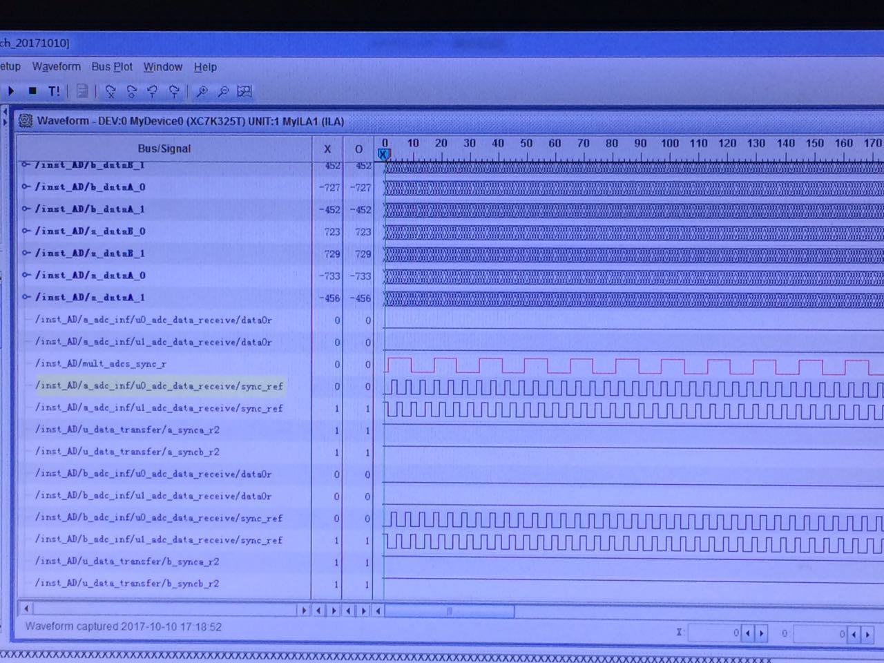
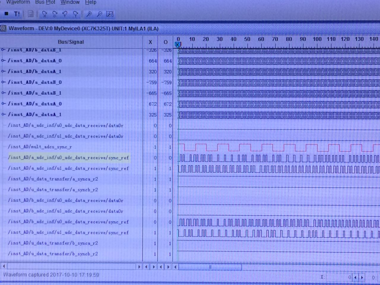
So, i think the adcs are not synchronized correctly and i suppose whether i operate with some wrong steps?

And you can contact me via email, my email  address is zhouleichen@163.com

Thanks,

ZhouLc

  • Zhoulc,

    How many of these repeaters are you using? Are you sending them all a single pulse or a 32 clock cycle signal per the ADC data sheet? Are any of the 64 converters synchronized? How fast are you sampling at? Is there a chance there is a timing issue with the Xilinx device?

    Regards,

    Jim 

  • Hi, Jim,
    I attempt to test synchronization with 2 ads5407 and a fpga, and in my project, sample clk is 500MHz, so i have the fpga to produce a periodic pulse (15.625M) for sync input. All 2 sync signal is distributed by a buffer with low skew, and layout in PCB is at the same length. Moreover, two format sync signal, both periodic pulse sync and one time pulse sync, are all tested, and there is no improvement.

  • Zhoul,

    Can you send a screen shot of the outputs, CLK and SYNC_IN for the two parts? How many clock cycles are they off? Does this amount change from input SYNC to input SYNC rising edge? Have you tried just using a single SYNC pulse?

    Regards,

    Jim

  • figure 1 shows sync signal at ads5407 SYNC pin. As i said before, it's a 15.625MHz periodic pulse which repeat every 32 CLKIN(500MHz) cycles.

    figure 2 is chipscope view window,  red signal is the sync signal produced from fpga and the signal on board is just as figure 1. But sync_ref signals which get from syncout pins are not stable and periodic. I have tried one-time pulse but i had the same result.

  • Hi,Jim,
    I found the way to do with my problem on website below, and i suggest that TI could revise datasheet.
    e2e.ti.com/.../1481154
    Thanks,ZhouLC