This thread has been locked.

If you have a related question, please click the "Ask a related question" button in the top right corner. The newly created question will be automatically linked to this question.

ADS7924: Initialization and communication via Simulink

Part Number: ADS7924

Hello everyone,

I am trying to read some of the registers of my ADS7924 via I2C. I have it hooked up correctly to my F28377D controlCard 1.1. I am trying to do this via MathWorks Simulink (R2017a).

My problem is now that I do not receive any data from my registers. I suspect that my initialization is incorrect or incomplete. Currently I only attempt to switch the ADS7924 from the initial Idle mode to the Awake mode and afterwards to the Auto-Scan mode. Should I then already be able to read out for instance register DATA0_L? Are there further steps required in the initialization? Can someone provide me with some initialization code or even a Simulink version of it? Is there also example code for reading registers?

Thank you!

  • To specify a bit further, the steps of my initialization are:
    1. Set Mode Control to Awake mode (0x80).
    2. Set Interrupt Control to 0x00.
    3. Set Interrupt Configuration to 0x1C.
    4. Set Sleep Configuration to 0x07.
    5. Set Acquire Config to 0x00.
    6. Set Power-up Config to 0x00.
    7. Set Mode Control to Auto-Scan mode (0xCC).

    To receive data for instance from the Device ID register, I do the following:
    1. Set Mode Control to Awake mode (0x80).
    2. Attempt to receive data from the register with address 16h.
    3. Set Mode Control back to Auto-Scan mode (0xCC).

    I took these steps based on another threat here in the TI E2E Community: e2e.ti.com/.../344643 . Still my questions remain as before.
  • Hi Dennis,

    Thanks for the detailed information. We do not have any code examples for this device, but I'd be happy to work with you to debug what is happening.

    Can you capture your digital waveforms using an oscilloscope (ideally) or a program so that I can verify timing and the codes you provide during initialization? Specifically I'm looking for the Awake and Auto-scan portion of your initialization.

  • Hi Dennis,

    What is your pin A0 connected to? When programming the device, are you seeing the acknowledge bit?

    If you can capture the Awake and Auto-Scan commands with an oscilloscope it will help me with the debug process.
  • Hi Evan,

    I have been working together with the colleague who took care of the wiring of the ADS7924 yesterday. It turned out that he made a mistake when wiring the RESET pin. Now that we have the reset pin connected to 3.3V, I am more positive about the initialization itself. To answer your question: A0 is connected to 3.3V at the moment.

    As you can see in the attachments, I can successfully complete the transmission of the initialization commands. These are currently carried out only once at the beginning of my Simulink simulation. As far as I understand the output of my oscilloscope, the master sends data to register 00 twice and the slave acknowledges it.

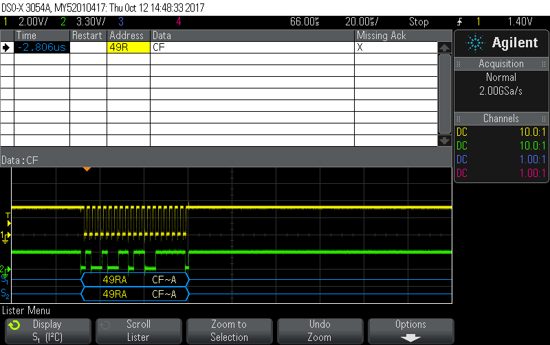
    Afterwards I want to read the contents of register 02 regularly. I trigger a Simulink subsystem, which contains the according blocks, regularly (every 0.1 seconds). On the oscilloscope however I see only the data "CC" (alternatively CD, CE or CF) sent to/from address "49R", but the acknowledge bit is missing (see second attachment). As the data CC to CF refers to the binary numbers "11001100" to "11001111" I suspect that this is my program scanning through Channel 0 to Channel 3 according to the description of the Mode Control Register. I would expect that for some reason the acknowledge bit is not sent in this case and therefore my slave never sends any data back to the master. How can I fix that? How do I manage to "insert" the acknowledge bit?

  • Hi Dennis,

    Thanks for the screenshots. From the ADC perspective, I don't see any issues. That said, I am not a digital expert so I am going to move this to the Delfino forum and will continue to help resolve any issues caused by the ADC.

    Delfino Team,

    Dennis has some questions about interfacing the F28377D with the ADS7924. I am not seeing any ADC issues but am not familiar with his processor. Can you help debug this?
  • Dennis,

    I believe I2C in F28377D is sending CC to CF. In that case I should be expecting ADS7924 (slave) to send the acknowledge signal. why are you expecting acknowledge signal from F28377D I2C?

    Also, how are sure that initialization sequence were communicated correctly? What is your I2C configuration?

    Regards,
    Manoj