This thread has been locked.

If you have a related question, please click the "Ask a related question" button in the top right corner. The newly created question will be automatically linked to this question.

ADC12D1600QML-SP: Quad Sub-Converter Like Spurs in Non-DES Mode

Part Number: ADC12D1600QML-SP
Other Parts Discussed in Thread: ADC12D1620QML-SP,

Hello,

I am using the ADC12D1600QML in a receiver application where:

Sampling rate (Fs) is 1280 MHz;
Input tone (Fin) is 539.9 MHz (~3 dB below full scale)
Demux (2:1) mode is used;
Non-DES mode is used;
Calibration run as indicated in dataheet

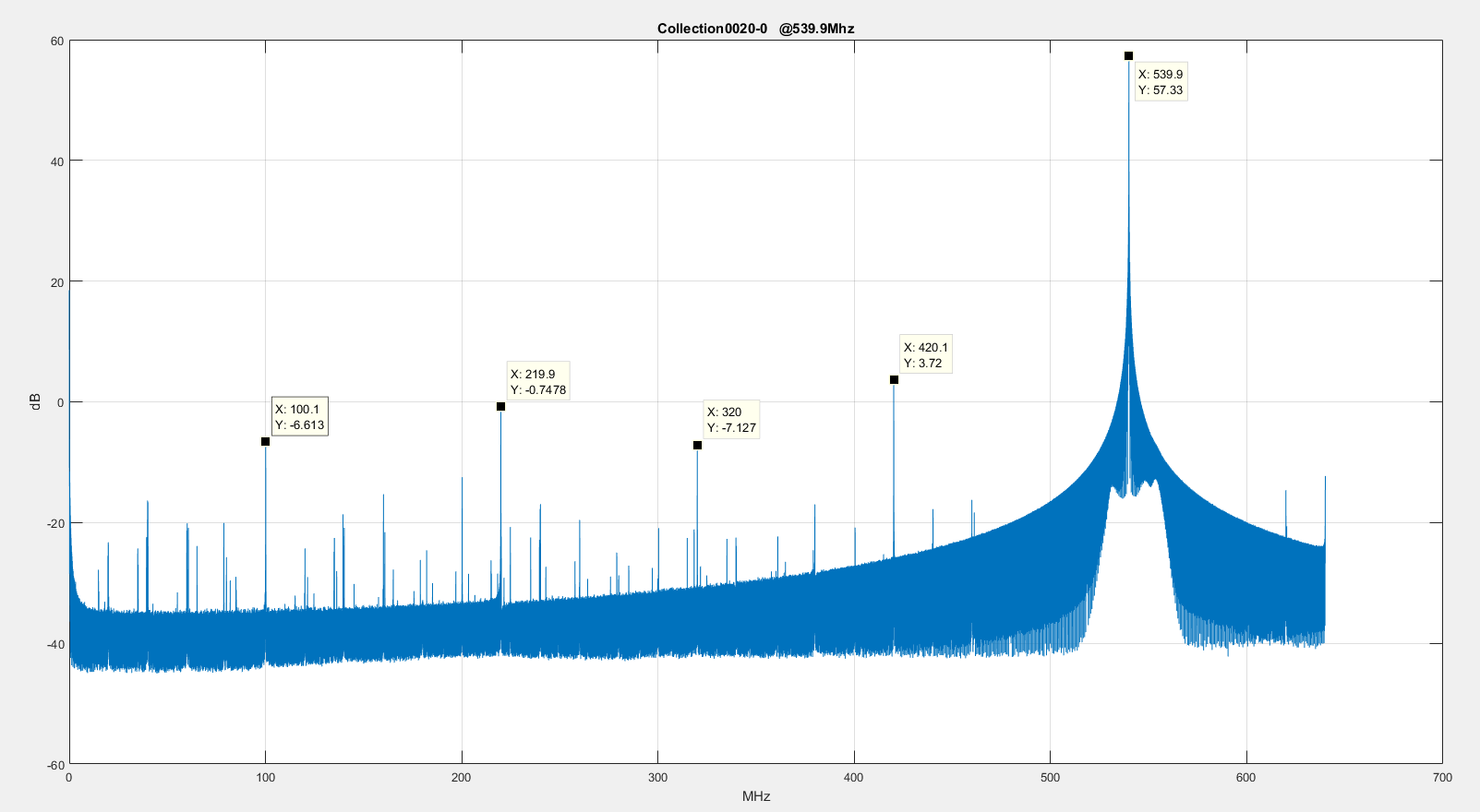
Collected data shows the expected fs/4 spur (320 MHz) due to DCLK coupling.  However, we are also observing spurs at Fs/4+Fin and Fs/4-Fin.  These spurs seem consistent with quad sub-converter operation (e.g.running in DES mode) but I am unsure why they are appearing in this Non-DES configuration.  The input tone is filtered such that all harmonics/spurs are -75 dBc.  Below is a "representative" plot of raw FFT data from the I channel. 

Any thoughts on why we may be seeing the Fs/4+Fin and Fs/4-Fin in non-DES mode would be appreciated.  

  • Hi Daniel
    I don't expect to see significant energy at Fs/4+/-Fin in that configuration.
    I will set up something similar on the bench and provide an FFT of what I see.
    Can you share the state of the configuration pins and all register settings you are loading if you're using Extended Control Mode?
    Thanks,
    Jim B
  • Hi Jim,

    Thank you for the quick response.  I will gather that information and send it to you.  Yes, we are using ECM for this application.

    Dan

  • Hi Dan

    Here is a comparative plot. This is taken using ADC12D1620QML-SP rather than ADC12D1600QML-SP. I definitely don't see any large spurs at Fs/4+/-Fin in this case.

    Regarding the ECM register settings there is one point to note for these space devices. For the ADC12D16x0QML-SP devices when using ECM mode, you need either write to all ADC registers after power-up in ECM mode, or toggle from non-ECM mode into ECM mode using the ECEb logic input pin. One of these methods must be used to set the default state of all registers.

    If you're not setting the defaults of all registers and then calibrating that might lead to improper mode or calibration results.

    Best regards,

    Jim B

  • Jim,

    Thank you for the plot and information about using ECM.  We are reviewing the power up sequence to ensure we are doing this as well as taking a closer look as to when/how we are doing calibration.  I will post our results/findings once this is completed.

    Dan

  • Jim,

    A few additional questions.

    • We are using the DCLK-to-Data phase relationship of 90°.  Could the DCLK transitions in the middle of each data cell be influencing this?
    • As you pointed out, We are using the 1600, not the 1620 (test data you provided).  Is there any reason to believe changes between the 1600 and 1620 would have improved this?  Our intent is to move to the 1620 in the future but our current design is being built with the 1600.

    Thanks,

    Dan

  • Hi Dan

    I don't think the DDR clocking DCLK to Data timing relationship setting will have a significant effect on the Fs/4+/-Fin spur magnitudes.

    Will your capture FPGA support operation with the DCLK in SDR mode? That would change the clock energy from CLK/4 to CLK/2 and may have some impact on the spurs.

    I did check into the differences between the '1620 and '1600 and one of the reasons for the package substrate re-design was to improve interleave spur performance in the LSPSM modes. I think that may also have some impact in the non-LSPSM operating modes.

    Best regards,

    Jim B