This thread has been locked.

If you have a related question, please click the "Ask a related question" button in the top right corner. The newly created question will be automatically linked to this question.

ADS1198ECGFE-PDK: Augmented leads calculation

Part Number: ADS1198ECGFE-PDK
Other Parts Discussed in Thread: ADS1198

Hello,

My name is Marcelo and I am trying to use the ADS1198ECGFE-PDK and the ADS1298ECG-FE software to understand the ECG signals and to compare them with a board my company is currently developing.

I am using a medical signals generator and I assume the PDK software is showing me the right outputs, because all the curves have the expected shapes.

I have also checked in the documentation (ADS1198ECG-FE Users Guide) the formulas to calculate the leads:

LEAD III = LL - RA - LA = LEAD II - LEAD I
aVR = RA - (LA + LL) / 2 = - (LEAD I + LEAD II) / 2
aVL = LA - (RA +LL) / 2 = LEAD I - LEAD II / 2
aVF = LL - (RA + LA) / 2 = LEAD II - LEAD I /2

My problem occurs when I compare the values from the curves and the ones obtained with the formulas for aVL and aVF:

LEAD Medium Peak Base Small Peak Base Large Peak
I 0.00025 0 0.0001 0 0.0008
II 0.00095 0.00085 0.0009 0.00085 0.0013
III (SW) 0.0007 0.00085 0.0008 0.00085 0.00045
III (formula) 0.0007 0.00085 0.0008 0.00085 0.0005
avR (SW) -0.00065 -0.0004 -0.0005 -0.0004 -0.0011
avR(formula) -0.0006 -0.000425 -0.0005 -0.000425 -0.00105
avL (SW) 0.0005 0.00042 0.00045 0.000425 0.000625
avL (formula) -0.000225 -0.000425 -0.00035 -0.000425 0.00015
avF (SW) 0.00015 0 0.00005 0 0.0004
avF (formula) 0.000825 0.00085 0.00085 0.00085 0.0009

Can anybody help me figuring out what is the correct formula to use? And what is the formula the software really uses in the augmented lead calculation?

Thank you.

  • Hello Marcelo,

    Thanks for your interest in our ADS1198!

    Your calculations are correct, except I see a typo in the first line. Lead III = LL - LA (remove the "-RA"). Other than that, the equations match what the GUI source code shows as the calculations. For your reference, the LabVIEW source code is available on the EVM product folder.

    One possible explanation for the difference in signal amplitudes may be how you have the electrodes connected to the ADS1198ECGFE-PDK. The software is expecting the electrodes to be connected to certain channel inputs in order for the calculations to work properly. Can you confirm that your electrode configuration matches the EVM schematic?

    Best Regards,

  • Hello Ryan,

    Thank you for your response, sorry for the delay in replying.

    I have checked several times and the leads are connected as expected (following your image).

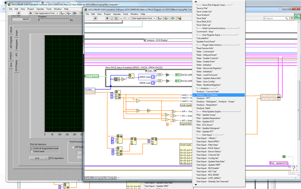
    You mentioned I could check the source code, but I couldn't find the lead calculation part, could you tell me what is the file that contains this procedure?

    Thank you.
  • Hi Marcelo,

    Honestly, I'm not that familiar with LabVIEW myself, so I apologize if this explanation isn't the most clear. I simply opened the main LabVIEW project "ADS1298evm.lvproj," navigated to the Analysis Tab -> ECG Display, and opened the source for the display by double-clicking on the scope screen. If you change the pull-down menu option to "Analysis - ECG Display," you will see where the various leads are calculated. Hopefully the image below shows you what I'm talking about:

    Best Regards,