


Part Number: ADS1294R
This topic is an add-on to my previous post regarding an external reference. A short intro to the problem: A low-power battery-driven system shall be utilized to measure respiration with ~10Hz. To minimize power consumption the ADS is only turned on for measurement and then powered down again. The internal reference is too slow (150ms) to follow this on/off-cycling, so I need an external one (comparable to the recommended design as shown in the ADS129xR datasheet).
Regarding pwr consumption I cannot ignore the fact, that the buffer caps are always discharged by the 10k input resistance of the VREF-pin. My measurements revealed that just turning the ext. reference on and re-charging that buffer-caps requires almost 25% of the total charge from the battery within a single sampling cycle.
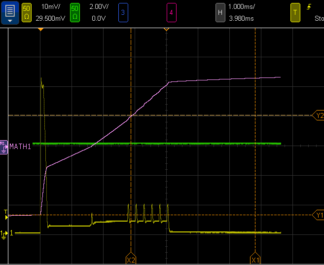
Example for a single sample - the yellow line is the current measured on a 1.7R-shunt from the battery and the pink line is the time-integral. The reference is turned on and gets ~1.5ms to settle, then the ADS is activated and 6 samples are taken (spikes arise from MCU running on full speed during SPI-communication). Afterwards the ADS is powered down again. Notice the current-spike for the first 200us which results from re-charging the 10uF reference caps.
The internal reference circuit (datasheet fig 31) has 22uF for the VCAP1 (ok, that's the low-noise not-yet-buffered voltage) and another 10uF at the VREFP-pin.
If I understand the ext. ref. circuit (fig 32) right then the main topic of that circuit is to buffer and (!) react on a dynamic (!) load of the VREFP-pin. However, as this reference voltage has to be utilized by up 4 (or 8) Sigma-Delta-ADCs I ask myself if that reference is internally buffered (the input has a 10k resistance which has to arise from something). In that case I could reduce the 10uF to 1 or 2uF and use e.g. 100R instead of 10R for the op-amp-output (I know that this filtering is only necessary for the opamp's own noise).
Any ideas or suggestions?
