This thread has been locked.

If you have a related question, please click the "Ask a related question" button in the top right corner. The newly created question will be automatically linked to this question.

ADS1298: Problem with signal sampling at 16kHz data rates.

Part Number: ADS1298
Other Parts Discussed in Thread: ADS1299,

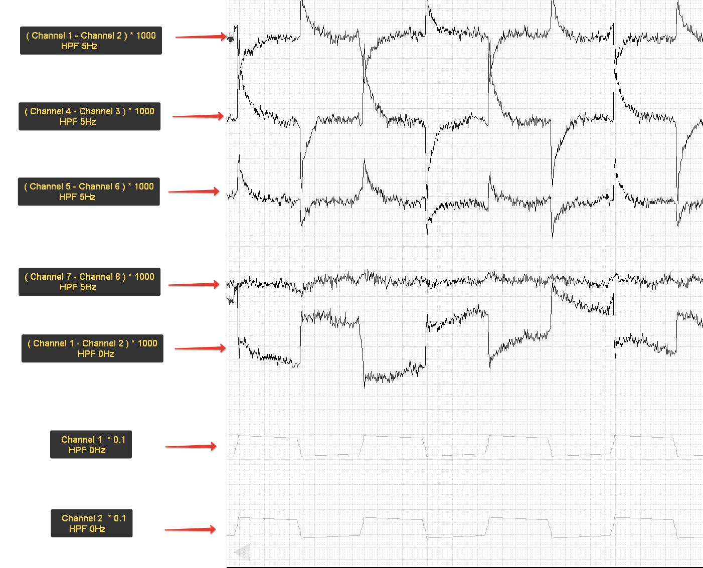
We use ADS1298 at 16000sps data rate for sampling 2Hz square wave (PGA gain 6, internal reference 2.4V, AVSS - 2.5V, AVDD +2.5V)

We connect square signal(200mV, 2Hz) to Auxiliary Differential Input TESTP_PACE_OUT1(+) and TEST_PACE_OUT2(-) and multiplex it to all eight channels.

And we see difference between some channels. But for example Ch7-Ch8 there are no difference. We tried to do it on multiple number of ads1298 and results was the same. What may be the problem?

  • Hello Dimitry,

    Thanks for your post.

    How are you generating the Channel X - Channel Y plots? Are you doing the arithmetic in post-processing?

    Each channel in the ADS1298 should be synchronized to the same clock cycle, so I would expect that the difference between channels with the same input signal would all look like Ch 7 - Ch8. Do you see the same results when using the internal test signal? What happens when you reduce the data rate, say to 1kSPS?

    Best Regards,

  • Hello Ryan!
    Thanks for answer!

    Yes we do arithmetic in post-processing.
    Amplitude of internal test signal is very low and we don't see such results (Channel X - Channel Y amplitude is lower than noise level).
    We have checked a number of ADS1298. And noticed that the first channels in all ads1298 have a deviation from other channels(at high-frequencies signal >2kHz or high-amplitude signals). Unfortunately, we have not yet managed to compensate for this deviation by using simple coefficients. We think that problem is not related to the PCB layout because we were trying to use Auxiliary Differential Input for simultaneous multiplexing signals at all channels. The problem persists at 8kHz sampling frequencies. The lower frequencies are not interested for us.

    May be this problem is connected with datasheet remarks on page 13(SBAS459K):
    The presence of internal demodulation circuitry on channel 1 causes degradation of INL and THD. The effect is pronounced for full-scale
    signals and is less for small ECG-type signals.
    But this remarks applies to ADS129xR. May be some circuit on channel 1 present also in AD1298?

    We do not understand why this is happening.
    While ideas to try ADS1299.
  • Hello Ryan! 

    we tried to use ads1299 and fount that problem was gone.

    this means that ADS1298 also contains the internal demodulation circuitry on channel 1 like in ADS1298R and it causes degradation of INL and THD on channel 1.

    we are very pleased that we found the problem, but it took us quite a long time.

    Remarks on page 13(SBAS459K) of datasheet applies not only for ADS129xR devices, but for all ADS1298 family.

    maybe this info will help someone.

    Thanks.

  • Hello Dimitry,

    I'm glad that you found the issue, thanks for the update! I will discuss this with our designers and propose the changes you mentioned for the datasheet. However, the demodulation circuitry is only present on channel 1. Therefore, I believe the second and third waveforms ([CH4 - CH3] and [CH5 - CH6]) should look more like [CH7 - CH8].

    Do you by chance have the raw data from each individual channel in the tests above?

    Best Regards,